
Introduction
All files (including 3D printing files) can be found on our v2 satnogs-rotator repository here:
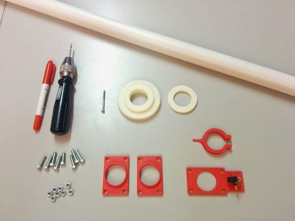
Tools
Parts
- Axis side × 4
- Ball bearing holder Cap × 3
- Worm gear × 2
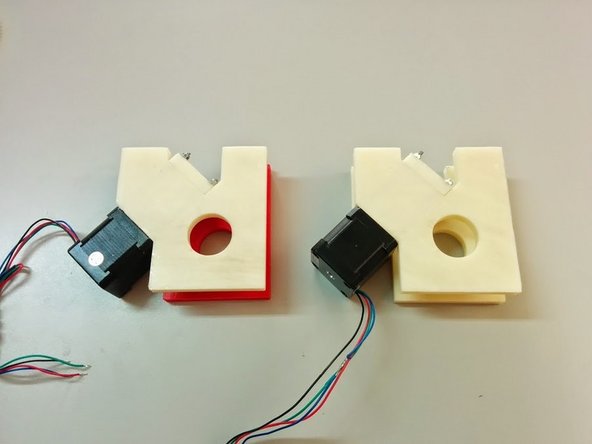
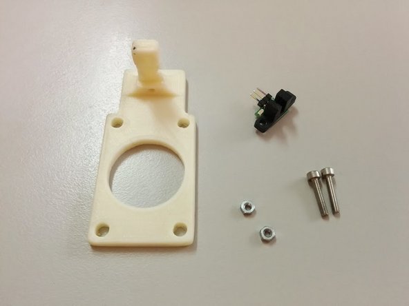
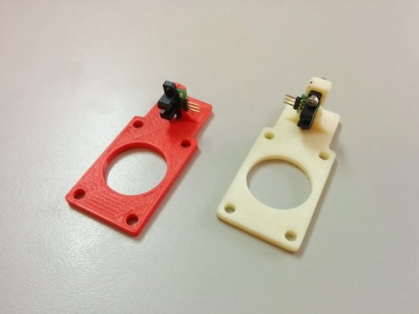
- Homing sensor holder × 2
- Axis gear × 2
- Axis gear spacer × 2
- Axis Bushing × 3
- Homing Ring × 2
- Azimuth Pillar
- M3 threaded rod × 8
- M3 x 16mm × 8
- M3 x 50mm × 2
- M3 x 25mm × 2
- M3 x 20mm Headless screw × 2
- M3 Nyloc nut × 8
- M3 nut × 5
- M5 nut × 12
- M3 washer × 12
- M5 washer × 20
- NEMA 17 × 2
- 608RS × 3
- H21LOB with Breakout × 2
- 1SL0828A00
- Silicone Based Grease
- M5 x 18mm × 12
- M4 x 20mm × 16
- M4 nut × 16
- O-ring ISO3601-026 ID31.47mm C S1.78mm × 6
-
-
Start with your enclosure box. We are using an ABB 1SL0828A00 IP55 box.
-
-
-
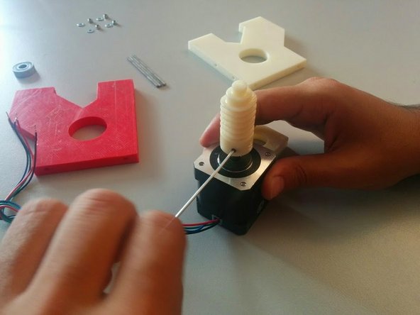
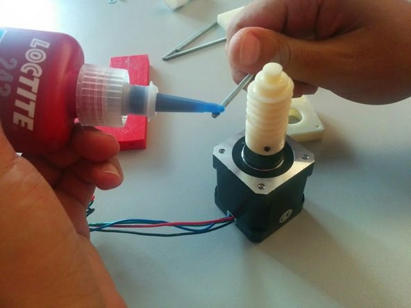
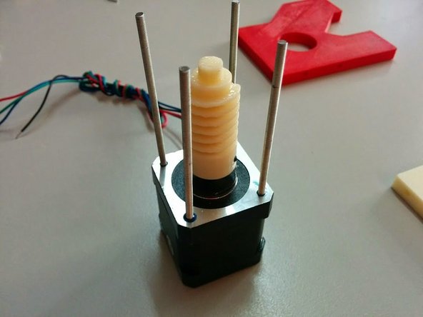
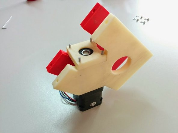
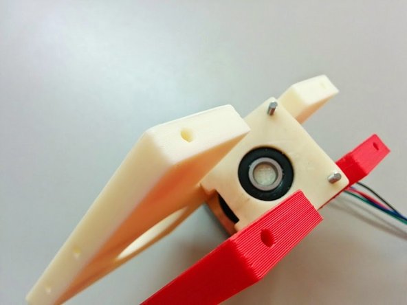
In this step we will be assembling the gear assembly for one axis.
-
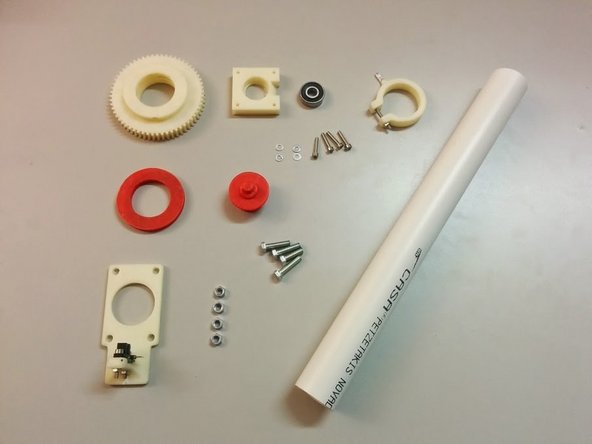
You will need: 1x Stepper Motor NEMA 17, 4x M3 x 70mm threaded rods, 4x M3 Nyloc nuts, 4x M3 washers, 1x 608RS Ball Bearing, 1x M3 x 20mm Headless screw, 2x Axis Side 3D printed, 1x Ball bearing holder Cap 3D printed, 1x Worm gear 3D printed
-
-
-
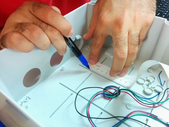
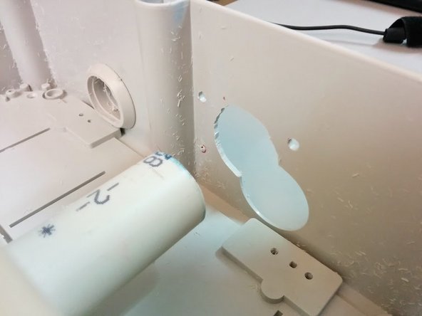
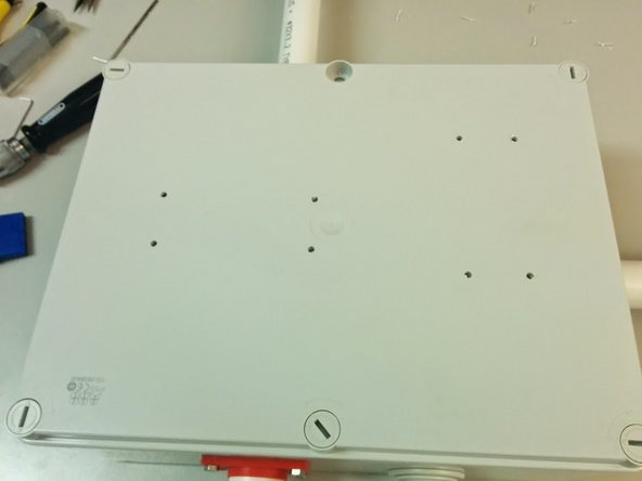
Next step is to mark the holes on the box. For this version we are not using an optimal box, and you should prefer a box without existing holes.
-
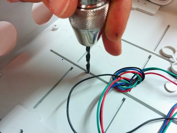
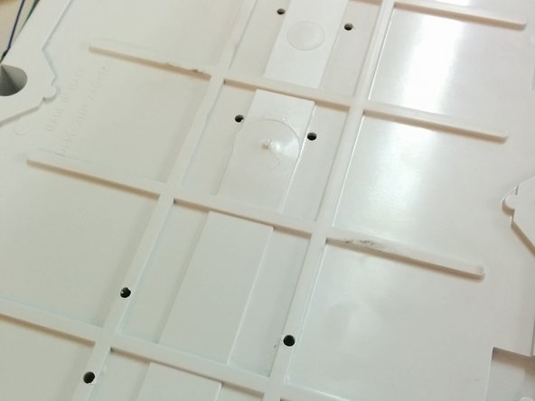
Start by marking the bottom 8 holes for the gear assemblies.
-
Positioning should be driven by the axis lines. Try to center those axis lines within the box. Keep in mind that the 4 holes of each axis are creating a 60x31mm rectangle.
-
Drill the holes (a hand drill might be easier to use).
-
-
-
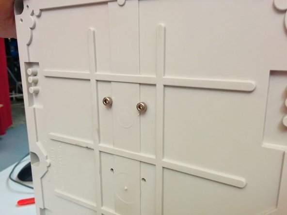
We now need to mark the side holes for the axis. For that we will need aprox 200mm (fits in the box) of the axis tube (Φ32)
-
Insert the small axis tube in a gear assembly, then 2 M4 Bolts to temporarily hold the gear assembly to the box. Remember this is simply for marking.
-
Repeat the process for the other axis.
-
-
-
Altitude Axis Assembly You will need:
-
Φ32 PVC tube 1.2m
-
3D printed parts: 1x Axis gear, 1x Axis gear spacer, 2x Axis Bushings, 1x Homing Sensor Holder, 1x Homing Ring
-
1x M3x50mm bolt, 8x M5x18mm bolts, 16x M5 Washers, 8x M5 nuts, 1x M3 x 25mm
-
4x O-rings, to put in Axis Bushings
-
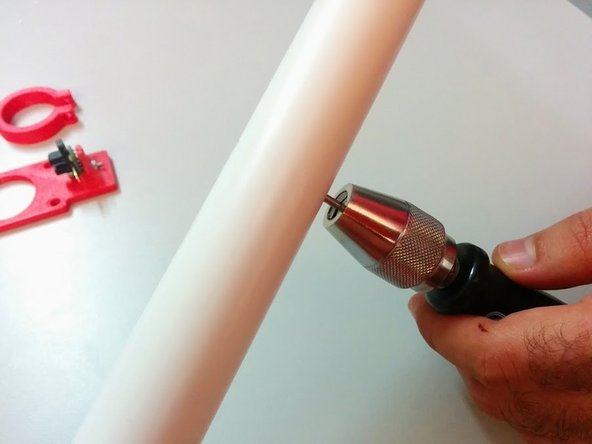
Cut a Φ32 PVC tube at aprox 1.2m length. Mark the center of it and drill two M3 holes opposite to each other.
-
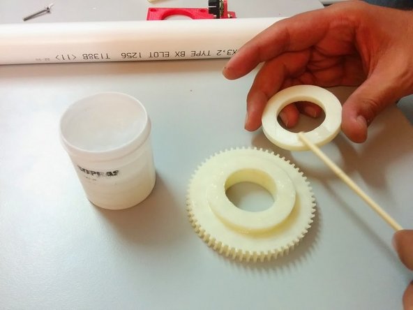
Apply Silicone Based Grease in Axis Gear sides, Axis Gear Spacer sides and Axis Bushing O-rings.
-
-
-
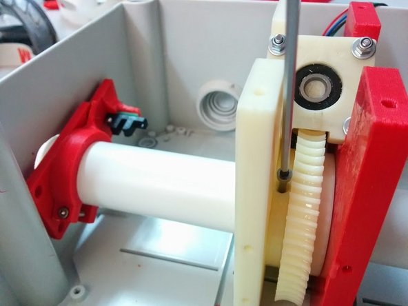
Slide the Axis Gear and Axis Gear Spacer in place inside the gear assembly of Altitude, making sure the Axis Gear is oriented in a side you can then screw the bolt that holds it to the Axis Tube.
-
Slide the Axis Tube more than half a way in, but not exit the box.
-
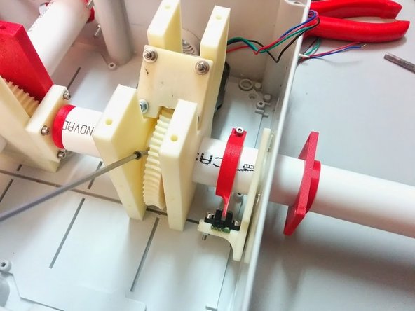
Make sure to slide the Axis Tube inside the Homing Ring and then the Homing Sensor Holder before it exits the box. Then align the tube so you can put the M3x50mm bolt that holds the Axis Gear to the Axis Tube.
-
Tip: Homing Ring should have such direction, that would enable you to adjust its fastening bolt (M3x35mm)
-
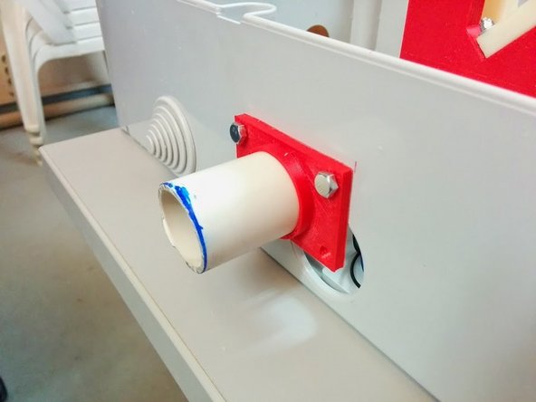
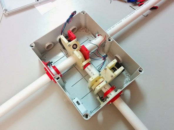
Place the outer Axis Bushings on both sides and fasten them to the box using the M5x18 bolts and M5 washers and nuts.
-
-
-
Azimuth Axis Assembly You will need:
-
Φ32 PVC tube 30cm (this would depend on where you will mount SatNOGS on, in our case we will be using the SatNOGS tripod v2)
-
3D printed parts: 1x Axis gear, 1x Axis gear spacer, 1x Axis Bushing, 1x Homing Sensor Holder, 1x Homing Ring, 1x Azimuth Pillar, 1x Ball bearing holder cap
-
1x M3x50mm bolt, 4x M5x18mm bolts, 4x M5 Washers, 4x M5 nuts, 1x 608RS Ball bearing, 1x M3 x 25mm, 1x M3 nut, 4 M3 x 16mm, 4 M3 small washers
-
2x O-rings for Axis Bushing parts.
-
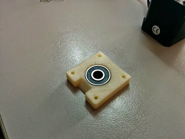
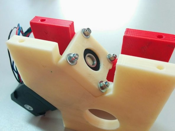
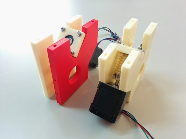
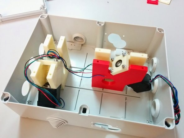
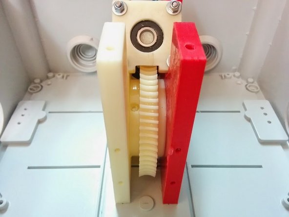
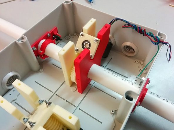
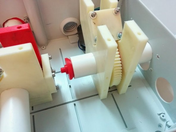
Screw the Ball bearing holder cap using M3x16mm and washers to the Altitude Gear Assembly as shown. Place the 608RS ball bearing in the holder cap.
-
Grease Axis Gear and spacer as before and place them inside the Azimuth Gear Assembly.
-
Insert the Axis tube, slide it through the Gear Assembly and place the Azimuth Pillar on top.
-
-
-
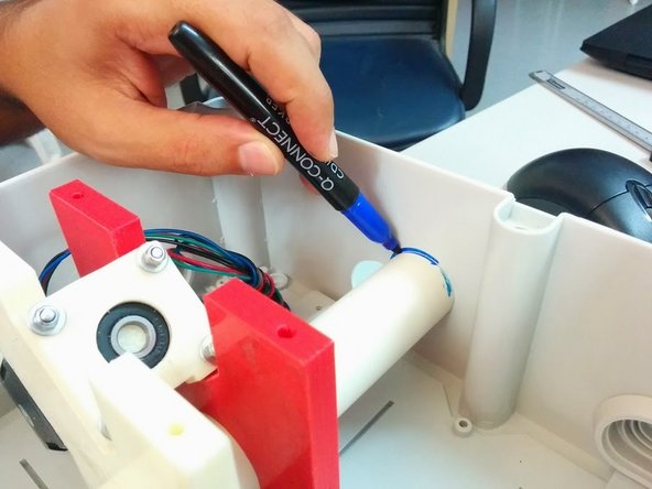
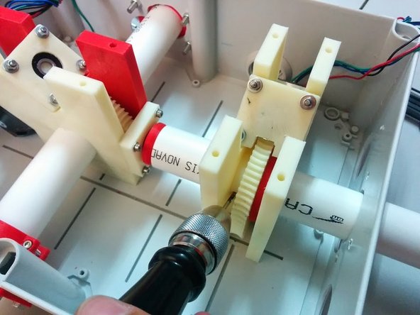
Slide the axis tube with the pillar all the way up and hold it firmly in place. Mark a whole in the tube for the Axis gear holding bolt.
-
Remove the axis tube, and open a through hole in the marked position on the axis tube.
-
Place the O-rings in Axis Bushing and apply Silicone Based Grease.
-
Re-slide the axis tube, making sure that you you also slide it through the Homing Sensor Holder and Homing ring before it reaches the Azimuth Gear Assembly.
-
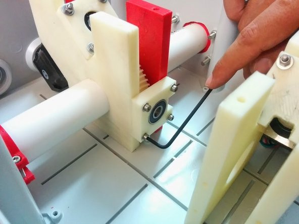
Screw the M3 50mm bolt of the Axis gear.
-
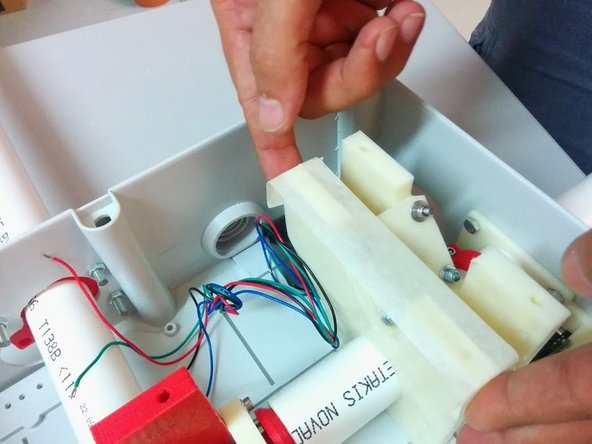
Screw all M5 bolts, washers and nuts for the Homing Sensor Holder and Axis Bushing outside the box.
-
Azimuth Axis is ready!
-
-
-
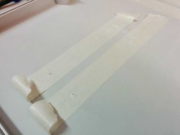
Apply masking tape on top of the gear assemblies reversely (sticking side up) notching the holes (4 for each gear assembly).
-
Place the cover of the box carefully and remove it to see the tape stuck underside with holes marked.
-
Drill holes on box cover.
-
Mechanical Assembly is now finished!
-
Electronics still need to be placed inside. Once they are in, you should use 8 M4 bolts to secure the cover of the box in place.
-


Cancel: I did not complete this guide.
2 other people completed this guide.

6 Comments
Hi, I am building the V2 rotator according this how-to - thanks a lot for the project. In the meantime, I have noticed that the bolts, which go through the box cover need some waterproofing. Also the proposed box from ABB does not fit, since there are the existing holes, which coincide badly - visible from the photos in the guide.
Adam Krovina - Resolved on Release Reply
links to the stl files seem broken. I didn't test them all but at least the first two are. namely Axis side and Ball bearing holder Cap
Jason Lewis - Resolved on Release Reply
FYI, it appears that 16xM4 screws (about 20mm long) and 16xM4 nuts need to be added to the BOM for the stepper assemblies to attach to the case, top and bottom. The latest axis sides include a well for the M4 nuts to reside so the M4 screws can hold on better.
Also add 12x M5x18mm bolts to the BOM (for the axis bushings and homing sensor holders). Thanks!
dosman -