
Introduction
Notes:
*Some of the pictures in this guide are from previous versions of the rotator.
-
-
In this step we are constructing the frame.
-
You will need 4x T slot 20x20 L160, 9x T slot 20x20 L102, 20x Hidden corner connection slot 6.
-
Start by assembling using a 2mm Allen key.
-
Beware of the correct hidden corner connection orientation.
-
You can find the assembly diagram on the next step.
-
If you purchased square nuts that only fit into the slot from the end, be sure to insert them before assembling the frame with the hidden corners.
-
-
-
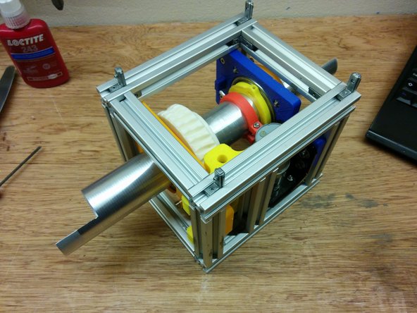
You should now have a complete frame.
-
Make sure you dont fasten the holding connectors for the extra L102 beam on one side.
-
Beware of the orientation (short side vs long side) of the hidden corners!
-
-
-
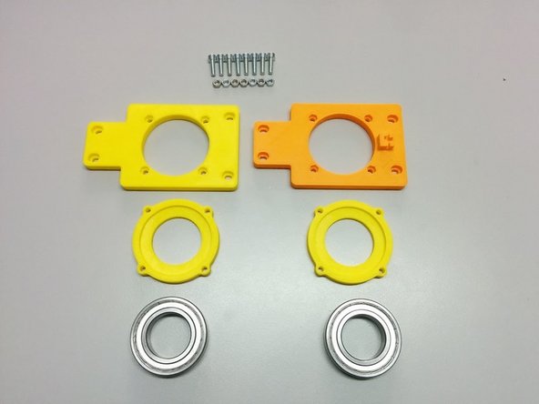
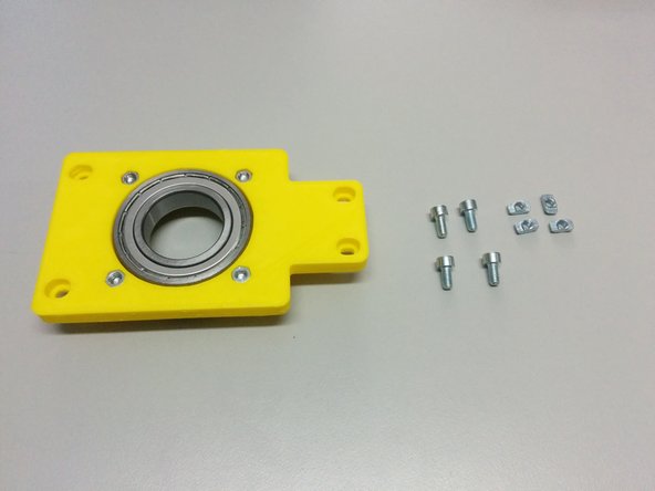
For this step you will need:
-
3D printed: Axis side with homing sensor (older version shown in the picture), Axis side, 2x Ball bearing housing
-
8x M4-20 screws, 8x M4 nuts
-
2x Ball Bearing 6008ZZ
-
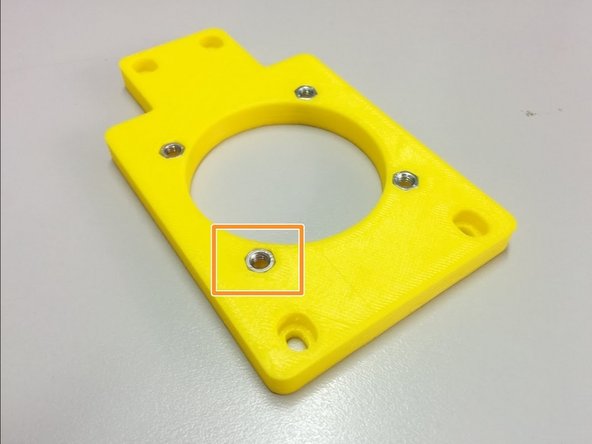
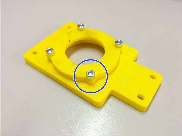
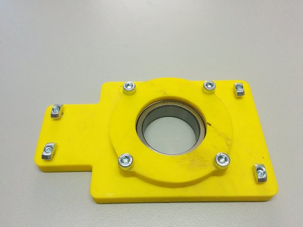
Insert the 8 nuts in the pockets of the axis sides.
-
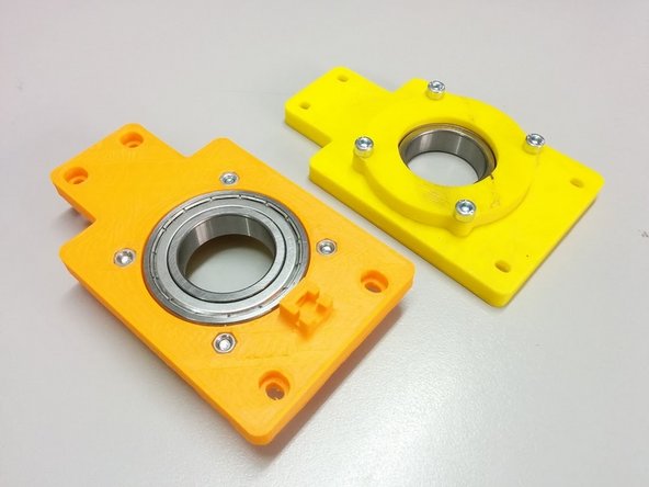
Attach the ball bearing housings on the back of each axis side and fasten it with M4-20 screws as shown.
-
-
-
In this step you will need:
-
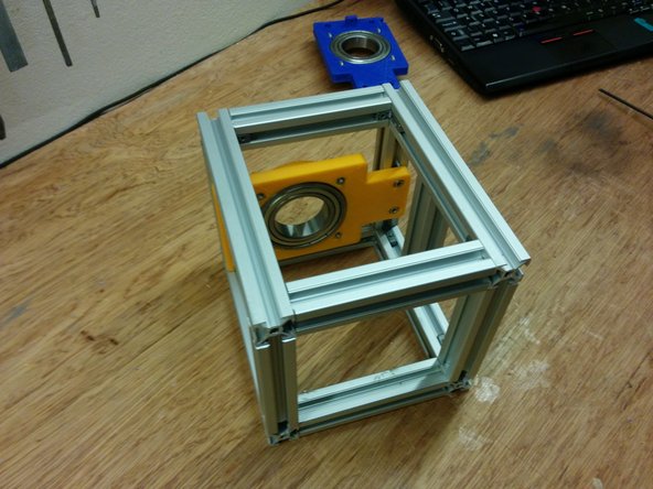
1x side assembly (the one without the homing sensor holder)
-
4x M4 slot 6 nuts, 4x M4-10 bolts
-
Screw the M4-10 bolts through the side assembly as shown on the second picture and attach the M4 slot 6 nuts
-
Finally slide the whole piece inside the frame as shown (bottom side touching the frame) and secure it by screwing the 4 M4-10 bolts.
-
-
-
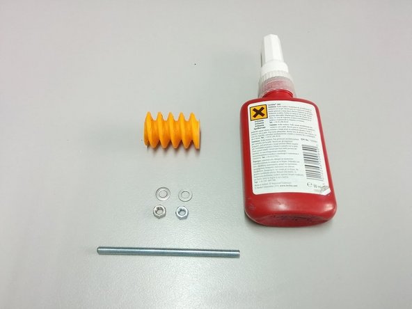
In this step you will need:
-
3D Printed: Worm gear
-
Thread lock glue
-
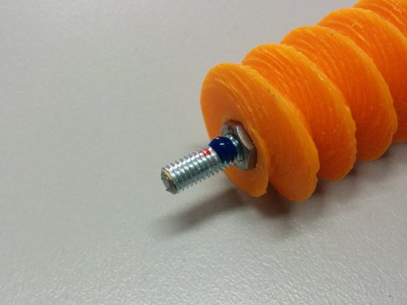
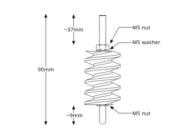
2x M5 nut, 1x M5 washer (wrong in the picture), 90mm M5 threaded rod
-
Apply glue as shown.
-
Follow the diagram for the dimensions.
-
-
-
In this step you will need:
-
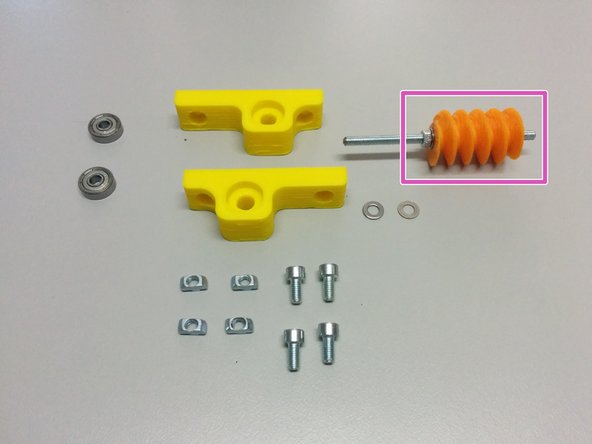
The previous worm gear assembly.
-
3D Printed: Worm mount
-
2 ball bearings 625ZZ
-
4x M4 nut slot 6, 4x M4-10 screws, 2x M4 washer.
-
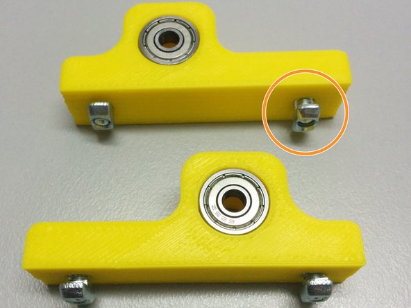
Insert the ball bearings inside the pockets of the mounts. Then screw the bolts into the nuts slot6 as shown in the pic.
-
Finally slide the worm mounts in the slot 6 rails as shown. First the one without the gear assembly first, then the second with the gear assembly as shown.
-
Don't forget the washers between the ball bearings and the worm gear assembly.
-
-
-
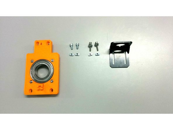
In this step you will need:
-
The second axis side assembly (the one with the homing sensor holder)
-
2x M4 slot6 nuts, 2x M4-10 bolts
-
2x M4 slot6 nuts, 2x M4-20 bolts
-
The motor mount.
-
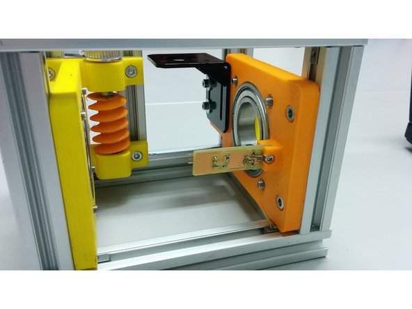
Attach the bolts, slot 6 nuts and the stepper motor mount.
-
Finally attach the whole assembly to the frame as shown in the picture.
-
-
-
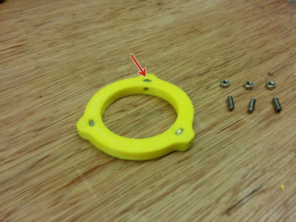
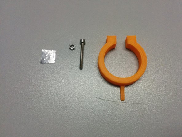
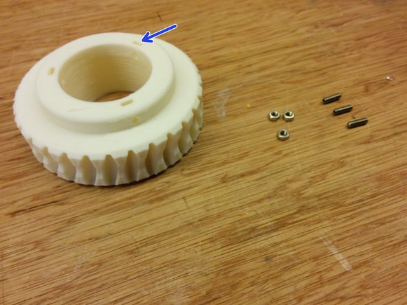
In this step you will need:
-
3D printed: Axis spacer collar
-
3x M3 nut, 3x M3-10 set screws
-
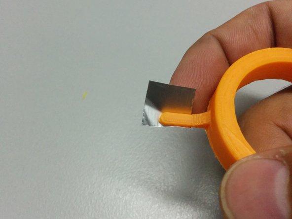
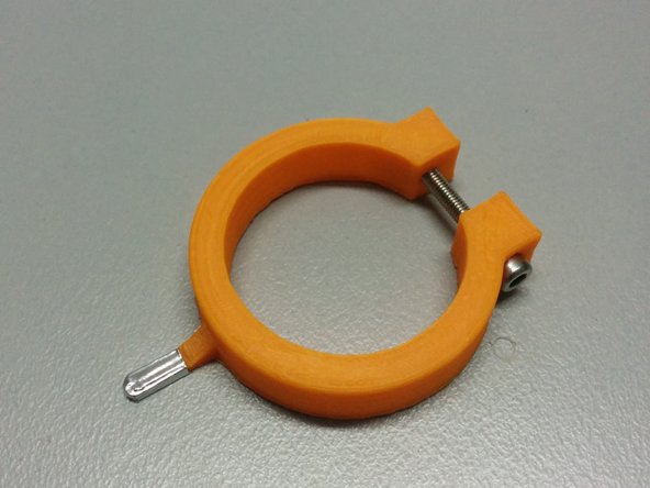
Insert the nuts in the pockets of 3d printed part, then screw the set screws as shown.
-
-
-
Insert the M3 nuts to axis gear part.
-
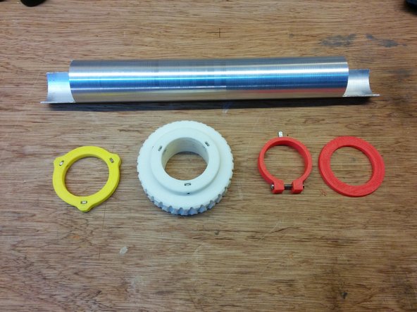
Pass the axis through:
-
Axis collar spacer
-
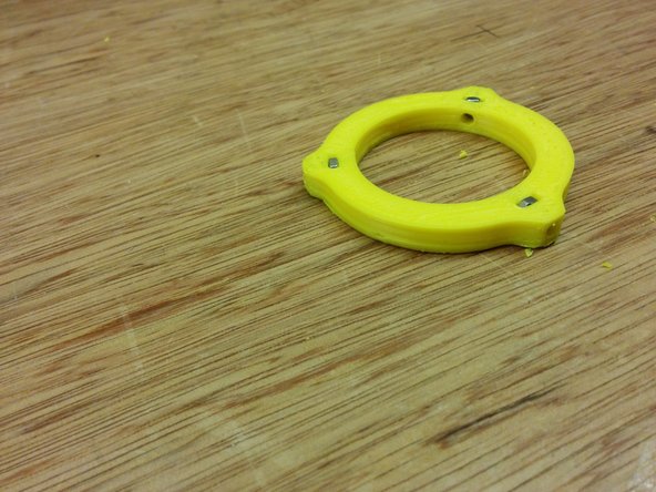
Homing ring
-
Axis gear
-
Axis spacer
Hello, good evening, 73, well I'm interested in a Rotor like this, can any colleague build the parts and sell it with bearings and parts, any tips???
Carlos Luis - Open Reply
-
-
-
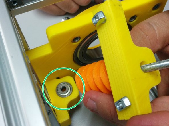
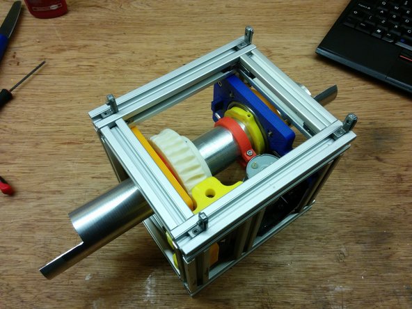
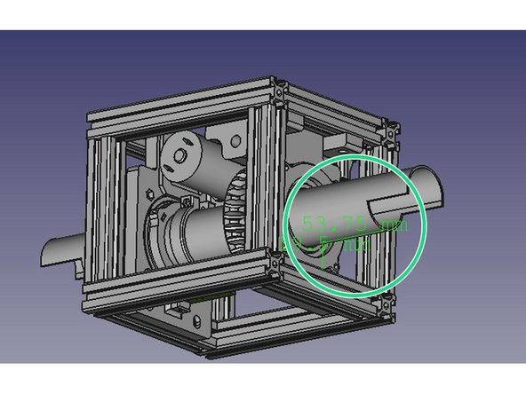
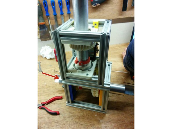
Ensure that the distance from the tube to the frame is approximately 54mm as shown in the first image.
-
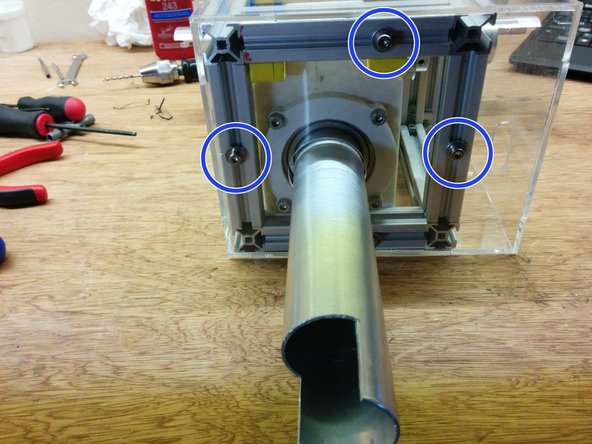
Tight all screws on axis gear part.
-
Apply some silicone grease on the axis gear and use a power drill to slowly run the worm gear for a couple of minutes in both directions .
-
-
-
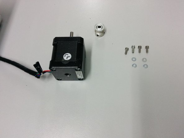
In this step you will need:
-
4x M3-6 and 4x M3 washers
-
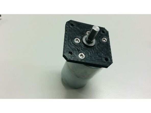
NEMA 17 stepper motor
-
GT2 pulley 20 T 5mm bore and GT2 pulley 36 T 5mm bore (not shown on the first picture)
-
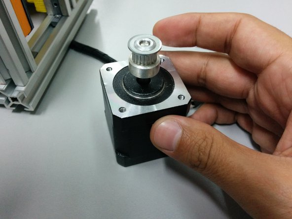
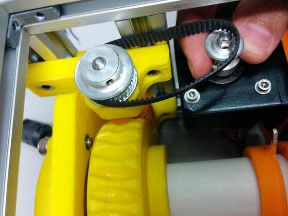
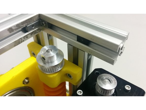
Pass the small pulley through the stepper motor shaft and the larger through the worm shaft.
-
Place the motor under the mount and tighten the screws.
-
-
-
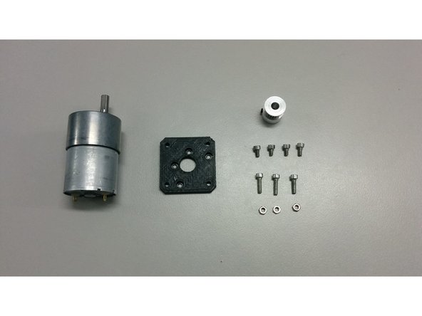
In this step you will need:
-
3x M3 nuts
-
4x M3-6 Head cap screws
-
3x M3-12 Head cap screws
-
3D printed part motor_mount_flange
-
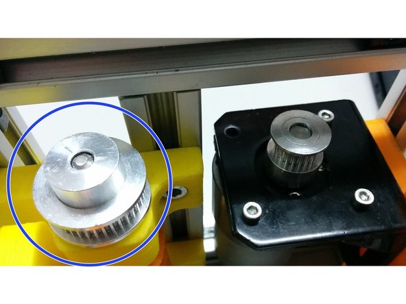
GT2 pulley 20 T 6mm bore and GT2 pulley 36 T 5mm bore (not shown on the pics)
-
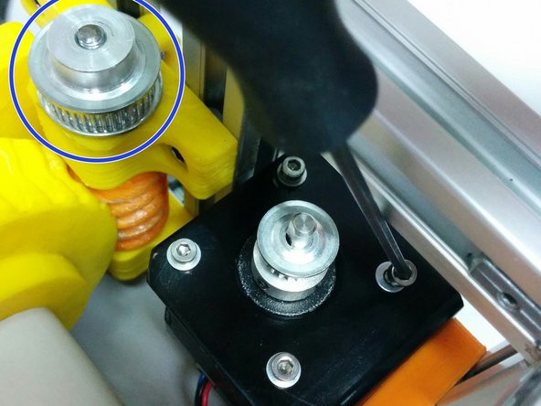
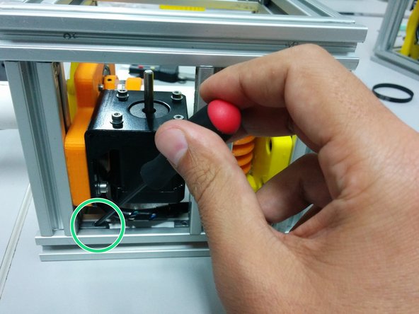
Bolt the motor on the flange
-
Insert the small pulley over the motor shaft and the larger through the worm shaft. Bolt the flange, with the motor, on the motor base.
-
-
-
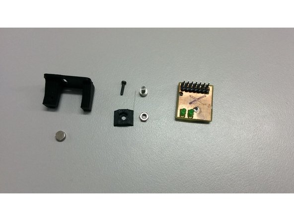
In this step you will need:
-
1x M3 nut
-
1x M3-6 Head cap screw
-
1x M2-6 Thread-Forming Screw
-
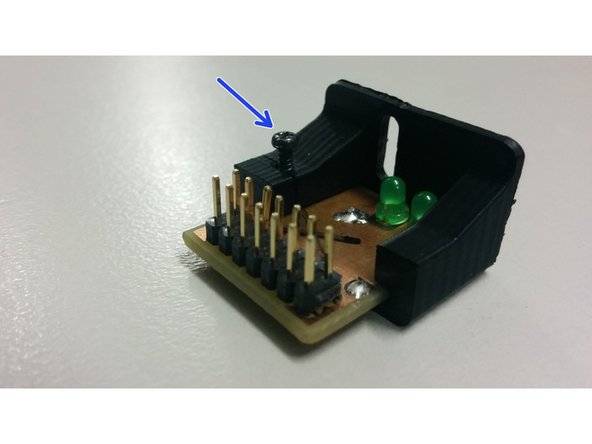
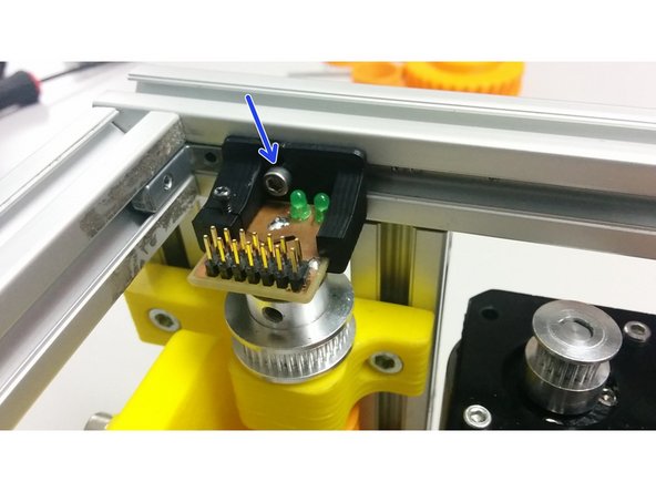
SatNOGS encoder board
-
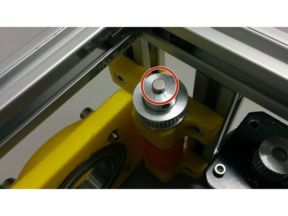
1x D6x2.5 Neodymium Diametric Magnet
-
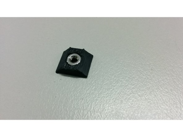
And 3D printed parts: M3_TSlot20_nut, encoder_holder
-
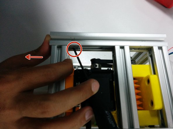
Place the nut into the 3D printed part and slide it into the aluminum profile
-
-
-
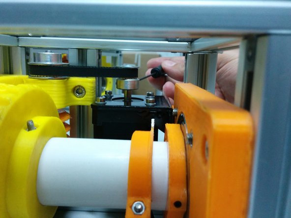
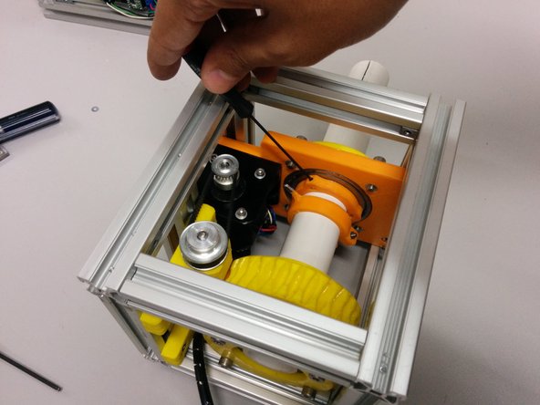
Slide The pcb into the 3D printed part and use the M2 screw to gently hold it in place
-
Using some cyanoacrylate glue, fix the magnet over the center of the pulley that is over the worm gear
-
Bolt and align the encoder over the magnet using the M3 screw
-
-
-
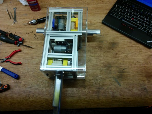
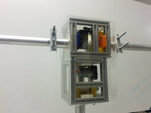
Assemble the elevation axis like the previous one.
-
Slide the hidden corners in the bottom side of the elevation axis as shown at the first picture.
-
Place the azimuth axis on top of the elevation in a way that the extension of the azimuth axis intersects with the elevation axis. The motors should be on the same side. Slide to the one side as shown in the picture.
-


Cancel: I did not complete this guide.
3 other people completed this guide.

16 Comments
are the 2020 lengths wrong because BOM and Wiki says L100 x 18 and L140 x 8?
BlueHashtagger - Open Reply
Hello guys,
I’m building the rotator in these days. I bought a standard “EU 2020” Hidden corner connection slot 6, but the sides of the “L” are too long (26mm) and in some cases interferes with other parts. The hidden corner that I see in the pictures seems to be shorter. Where have you bought them?
Thanks
OK, so where do the electronic boards boards go? How do you align all this up? There seems to be a lack of configuration management on what is out there on the website. I've been trying to piece this system together for well over a month and I am still confused on how these parts go together. Where is the azimuth section (since it doesn't have the boom going through both sides)? Where are the enclosure parts for weatherproofing? Does the Arduino board go inside one of these chassis or is it separate - if separate where does it go? How do you align the motors up so you know where you are point at boot up? I have a lot more questions than answers on this project.
This guide does not include details of adding the gt2 pulley to the worm drive assembly.
Ryan Turner - Resolved on Release Reply
I build one I have test the accuracy I have use a Ramps 1.4 PCB from a 3d Printer to check the first things.
https://www.youtube.com/watch?v=MmymUnJ-...
and now the next Step ........
Thanks for the Project !
Stemeh, could you please post the link where you found the D6x2.5 Neodymium Diametric Magnet. I'm having trouble finding them online.
Thanks,
Tyler
Hey,
We have not finished yet.
@houston chapman, you can check the BOM (https://github.com/satnogs/satnogs-rotat...)
Stay tuned!!
Tyler Cerrato, you can see the BOM of satnogs controller, https://github.com/satnogs/satnogs-rotat... .
Azisi, could you please post the link where you found the D6x2.5 Neodymium Diametric Magnet. I'm having trouble finding them online.
Thanks,
Tyler
I made a list of parts that doesn't include the 3d printed stuff. Could someone look over it to make sure i'm not missing something?
.
.
T connectors 3
M5-20 screws 8
M5 nuts 10
Ball bearing 6007ZZ 2
M5 slot 6 nuts 4
m5-10 bolts 4
thread lock glue
m5 washer 2
90mm M5 threaded rod
625zz ball bearing 2
m5-10 washer 2
m5 nut slot 6 4
m5-10 bolts 4
M3 nut 4
m3-12 bolt 1
m3 washer
m3-10 set screws 3
.
.
Also the guide could be more clear. The v2 guide is much better.
houston chapman - Resolved on Release Reply
I have the same question, is there a clear answer?
Wayde - Open Reply
While this and other instructions describe the lengths as L160 and L102, the 3.1 diagram here https://wiki.satnogs.org/File:C1050.png and the BOM specify L140 and L100 respectively. Which is correct?
Bruce Robertson - Resolved on Release Reply