
Introduction
This is a guide to build Helical UHF Antenna v4. The central frequency is 434Mhz and the antenna is can be Left-Hand or Right-Hand Polarized.
During all steps make sure to check with the Dimensions Table file https://github.com/satnogs/satnogs-anten...
Needed Files
All needed files are available in the SatNOGS Helical Antenna Repository: https://github.com/satnogs/satnogs-anten...
summary files for RHCP antenna in stl and dxf format
Helical-434-8-RHCP.stl
Helical-434-8-RHCP.dxf
summary files for LHCP antenna in stl and dxf format
Helical-434-8-LHCP.stl
Helical-434-8-LHCP.dxf
printable blueprint file for RHCP in dxf and pdf format
Helical-434-RHCP-printBase.dxf
Helical-434-RHCP-printBase.pdf
printable blueprint file for LHCP in dxf and pdf format
Helical-434-LHCP-printBase.dxf
Helical-434-LHCP-printBase.pdf
6 radial base file for plexiglass or polycarbonate base
Helical-434-6radialBase.dxf
Helical-434-6radialBase.pdf
plexiglass or polycarbonate triangular connector files
Helical-434-Triangle.dxf
Helical-434-Triangle.pdf
cooper matching triagle
Helical-434-CooperTriangle.dxf
Helical-434-CooperTriangle.pdf
dimensions table
Helical-434-8.xls
Characteristics calculation site.
http://www.vk2zay.net/calculators/helica...
All calculations are on axial mode
Any change of the pipes diameter must take into consideration the fact that they are attached on constant diameter of 220mm
Precise dimensions are provided on the files linked
For RHCP and LHCP antennas
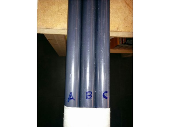
Letters A,B and C are marking the 3 PVC pipes
The RHCP design uses a Β-Α-C arragement and the LHCP a C-A-B arrangement
-
-
Position and secure the printout of the base on your workbench
-
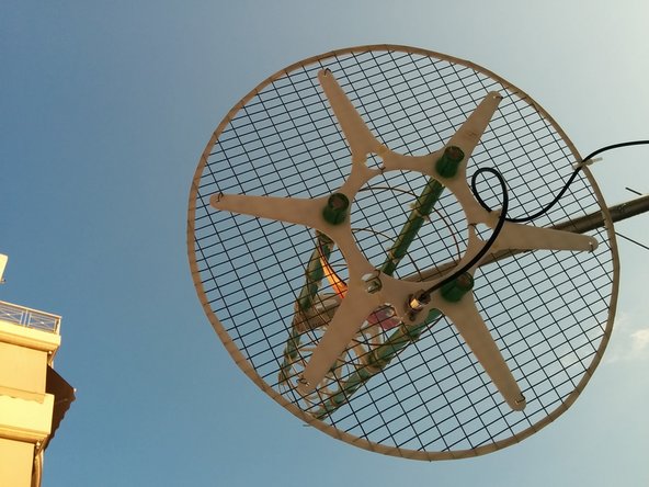
Position the reflector grid axially, and mark a perimeter of 552mm to cut.
-
Cut the the perimeter and adjust adhesive tape around it to avoid cutting ourselves.
-
Optionally after finishing up and positioning our antenna on a rotator tape can be removed.
-
-
-
Position the plexiglass 6 radial base on the corresponding mark on the printout. In the case of a LHCP antenna, follow the picture provided, for a RHCP antenna it should be vice-versa.
-
Stabilize the plexiglass on the printout using adhesive tape. Position the reflector on the plexiglass and use tie-ups and small wires to tie-up the six small peripheral holes and the 3 inner holes that will not be used to place PVC pipes through them.
-
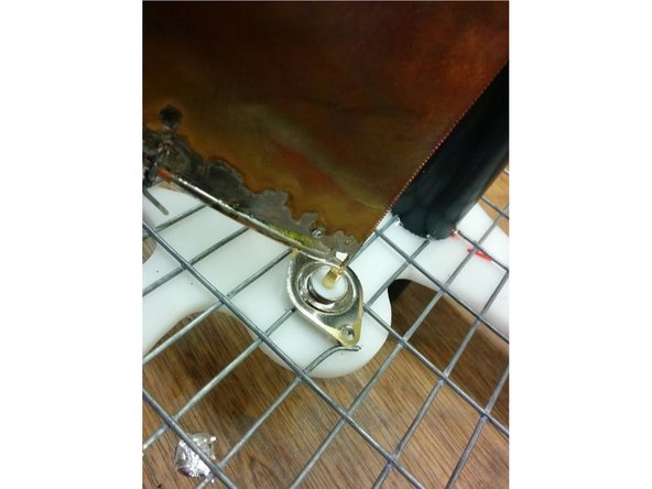
Cut the grid on the positions the pipes and the N-type connector will be placed.
-
-
-
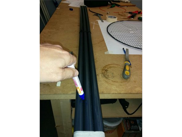
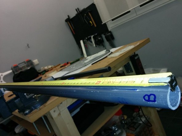
Cut 3 PVC pipes 1430mm long
-
Connect them in parallel and mark a straight line through all three of them
-
This line will be used for the horizontal positioning of the contacts with the helical and the triangular plexiglass supports.
-
Mark the bottom of your pipes as A,B and C
-
-
-
Mark the positions of the helical and the plexiglass supports on each pipe using the provided dimensions table starting by -40mm
-
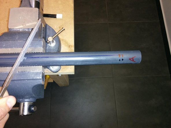
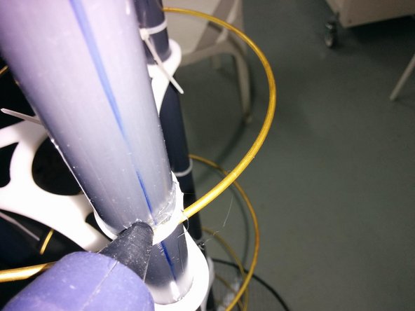
Create a small cavity, in angle using a small file, on the contact spots of the PVC pipes and the helical (Attention! Don’t create a hole, the angle must be around 15 degrees and it’s direction is dependent by the helical orientation. eg in the photo provides is for an LHCP antenna).
-
-
-
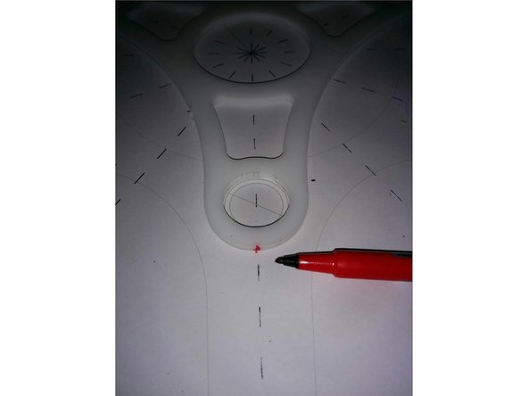
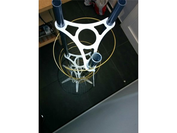
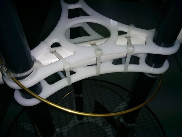
Using the printout mark the triangular plexiglass on the alligment of the tube center as depicted
-
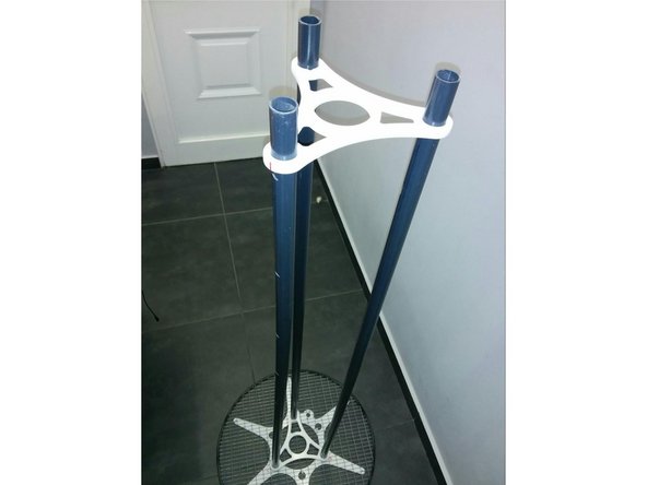
Position the tubes on the plexiglass base and adjust the triangular stabilizers on their corresponding positions
-
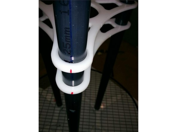
Turn the pipes to align to the marks on the triangular stabillizers
-
-
-
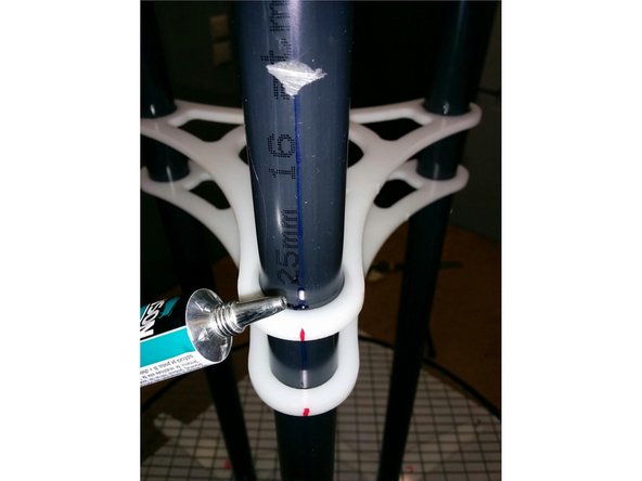
Apply PVC-plexiglass glue and stabilize the second triangular stabilizer first.
-
Don’t apply glue to the first stabilizer because it will be fixed on the final antenna application on the ground station.
-
Glue the basis and the third triangular stabilizer. Apply glue to both sides and let it be rigid.
-
-
-
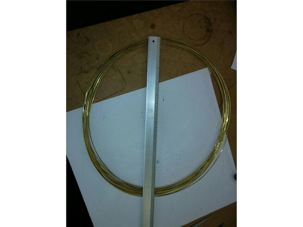
In our example we will use brass wire, 1.5mm wide from a 60cm diameter packaging. We cut more than 6m. (our final length shall be 5696mm).
-
Due to the fact that one turn equals 5696/8=712mm the diameter must be 712/π=226mm aprox. Turning must be clockwise or counter-clockwise depending whether it’s a RHCP or a LHCP antenna.
-
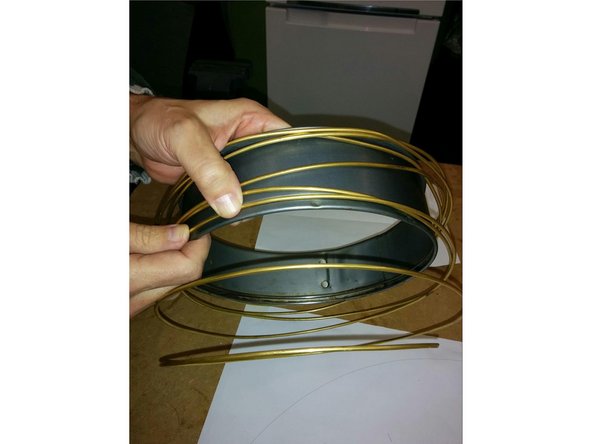
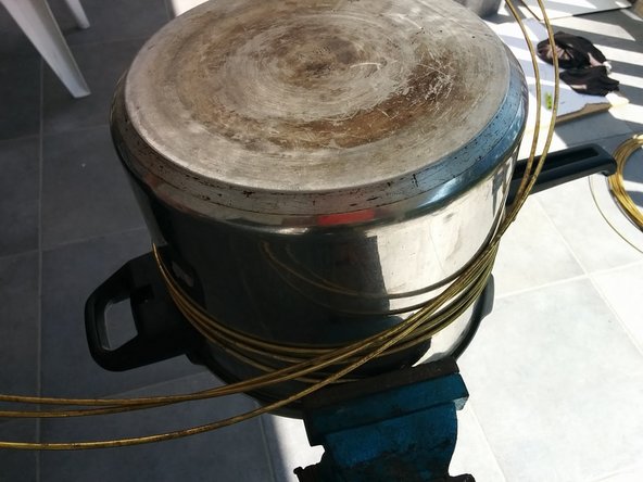
Using any cylindrical object (in our case kitchen ware) we turn the wire in 23-24cm perimeter.
-
-
-
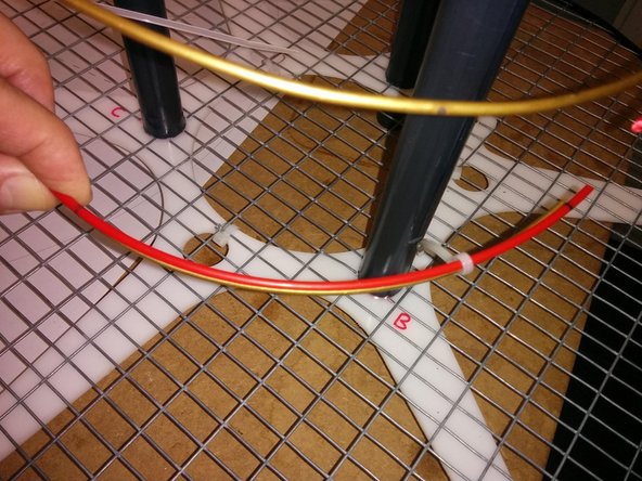
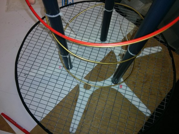
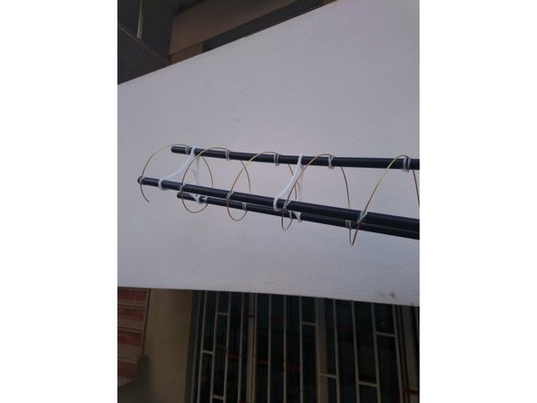
Position the helicoid around the three PVC pipes clockwise or counterclockwise depending on the antenna you want to build, (RHCP or LHCP). On the picture provided it’s an LHCP antenna.
-
At the basis of the helicoid we mark on the helicoid the PVC-helicoid contact positions according to the provided dimension table.
-
First mark from the base is at 178mm, from N-type connector to position B, next 23 marks every 237,3mm and you will get a 59mm free hanging cable in the end.To do so we used plastic ABS filament marked every 712/3=237,3mm
-
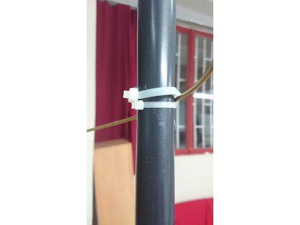
As soon as the positions of the helicoid are marked on the PVC pipes tire-ups should be used to initially position the helicoid to the PVC pipes, except at position B, during that it’s advised to constantly check the geometry and the proper positioning of the antenna.
-
-
-
Using hot glue, attach the helicoid to the PVC pipes on the cavities we created using the file in a previous step . Leave it to dry up and get rigid.
-
Using tire-ups over and under the cavities would provide even greater rigidness.
-
-
-
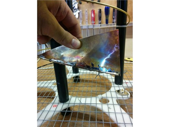
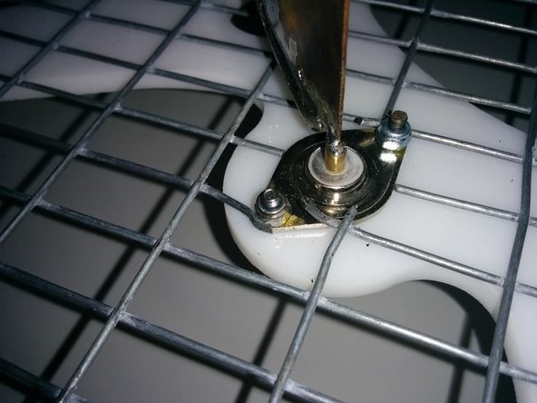
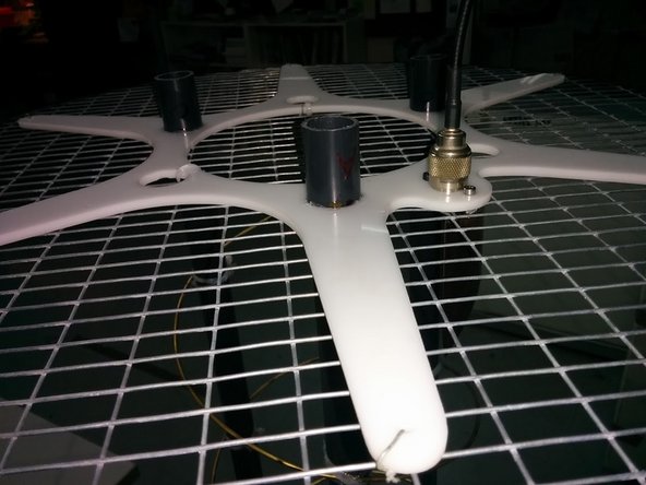
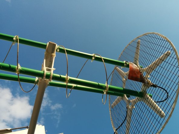
Place the N-type in position without screwing it. Cut, perforate and bend the triangular sheet of copper 0.5mm thick according to the design file provided. File the tip so it can be inserted in the N-type.
-
Stabilize the brass wire on the copper triangular using small wires, and solder them.
-
Insert the small tip of the triangular copper sheet in the N-type connector and solder.
-
Screw the N-type on it’s final position
-
Check with a multimeter that there is no short between reflector & helix
-
-
-
As soon as we are 100% sure everything is ok, cut the rest of the wire till you get a 5696mm length
-
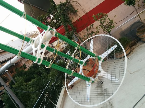
The final positioning is done on the plastic PVC pipe that has holes to tire up two plexiglass stabilizers.
-
Connect the co-axial to the N-type
-


Frequency 434 MHz
Turns 8
Weight: 2.2kgr
Circumference/Wavelength (0.75 - 1.33) = 1
Reflector Diameter/Wavelength (0.8 - 1.1)= 0,8
Turn Pitch/Wavelength (0.2126 - 0.2867) = 0,25
Wavelength (Λ) 691 mm
Winding Diameter 220 mm
Winding Circumference 691 mm
Winding Spacing 172 mm
Winding Length 5696 mm
Reflector Diameter 553 mm
Boom Length: 1.379 m
Gain: 18.711 dBic
Half-Power Beamwidth: 36.806 deg
Cancel: I did not complete this guide.
2 other people completed this guide.

3 Comments
Here is a NEC2 card stack for the helix. The gain is about 12 dBi.
CM Helix, SatNOGS, v4
CM Frequency: 434 MHz
CM Wavelength: 691 mm
CM c=299792458 m/s
CM Radius = 110 mm
CM Turns: 8
CM Circumference to wavelength ratio: 1
CM Reflector perimeter to wavelength ratio: 0.8 = 553 mm
CM Winding diameter: 220mm
CM Winding circumference: 691mm
CM Winding spacing: 172 mm
CM WInding length: 5696 mm
CM Reflector perimeter: 553mm
CM Total length = 172 mm x 8 t = 1376 mm
CM
CM Feedpoint(1) - Z: (110.310 - i 1156.800) I: (0.0001 + i 0.0009) VSWR(Zo=50 Ω): 99$
CM Directivity: 11.07 dB
CM Max gain: 12.70 dBi (azimuth 0 deg., elevation 90 deg.)
CM Front-to-back ratio: 0.00 dB (elevation 90 deg)
CM Front-to-back ratio: 0.00 dB (elevation of front lobe)
CM Front-to-rear ratio: 0.00 dB
CE
GH 1 500 0.172 1.376 0.110 0.110 0.110 0.110 0.003
SM 10 10 0.277 -0.277 0 0.277 0.277 0
SC 0 0 -0.277 0.277 0
GE
EX 0 1 1 0 1 0 0 0 0 0 0
FR 0 1 0 0 434 0
RP 0 90 90 0 0 0 1 4 0 0 0
EN
Here is a NEC2 card stack for the 8 turn helix. It computes about 12 dBi gain.
CM Helix, SatNOGS, v4
CM Frequency: 434 MHz
CM Wavelength: 691 mm
CM c=299792458 m/s
CM Radius = 110 mm
CM Turns: 8
CM Circumference to wavelength ratio: 1
CM Reflector perimeter to wavelength ratio: 0.8 = 553 mm
CM Winding diameter: 220mm
CM Winding circumference: 691mm
CM Winding spacing: 172 mm
CM WInding length: 5696 mm
CM Reflector perimeter: 553mm
CM Total length = 172 mm x 8 t = 1376 mm
CM
CM Feedpoint(1) - Z: (110.310 - i 1156.800) I: (0.0001 + i 0.0009) VSWR(Zo=50 Ω): 99$
CM Directivity: 11.07 dB
CM Max gain: 12.70 dBi (azimuth 0 deg., elevation 90 deg.)
CE
GH 1 500 0.172 1.376 0.110 0.110 0.110 0.110 0.003
SM 10 10 0.277 -0.277 0 0.277 0.277 0
SC 0 0 -0.277 0.277 0
GE
EX 0 1 1 0 1 0 0 0 0 0 0
FR 0 1 0 0 434 0
RP 0 90 90 0 0 0 1 4 0 0 0
EN
What is the connection impedance on foot of the antenna? Do you have a reference for the copper triangle design?
I think the 18dBi are over optimistic as is the webform calculator you reference to in the excel sheet maybe is not correct? The ones you used gave more conservative values 12-13dBd.