
Introduction
Bill of materials can be found here:
https://github.com/satnogs/satnogs-anten...
CAD drawing (and designs) can be found here:
https://github.com/satnogs/satnogs-anten...
The Emerson calculation model can be found here:
http://oldsite.rac.ca/en/amateur-radio/o...
Enter 437Mhz as the frequency and 8 turns.
-
-
We start by shaping up the wire.
-
Print and stick to a surface the design of your antenna
-
Cut a 8m piece of Galvanize Steel wire 2mm thick.
-
Using a cylinder slightly smaller than the radius of the helix (in our case 130mm) start wrapping the steel wire around it. Repeat multiple times, till it starts to approximate the needed diameter.
-
You should end up with a nice spring-like piece of steel wire.
-
-
-
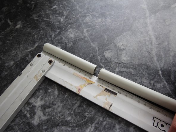
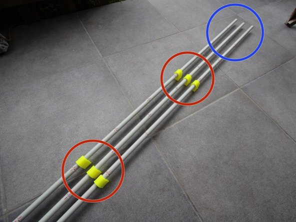
Next, we need to mark the PVC pipes
-
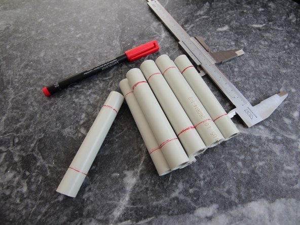
Cut 3x140cm Φ16 PVC pipes.
-
Using the design, mark the T-Holder positions on the pipes (3 each).
-
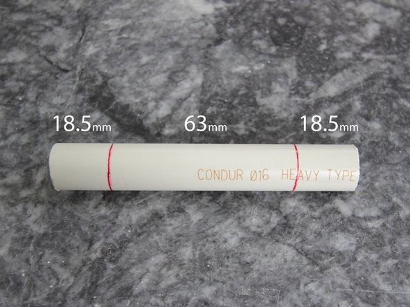
Then we need to mark the wire notches on the pipes. Consult the design for exact dimensions. 165mm is the spacing between marks for each pipe.
-
Make sure that on each pipe the marks are offseted by 1/3 of 165mm from the previous one. Refer to design if in doubt.
-
Finally, make the notches using a file (tool) on approx. 30 degrees inclination.
-
-
-
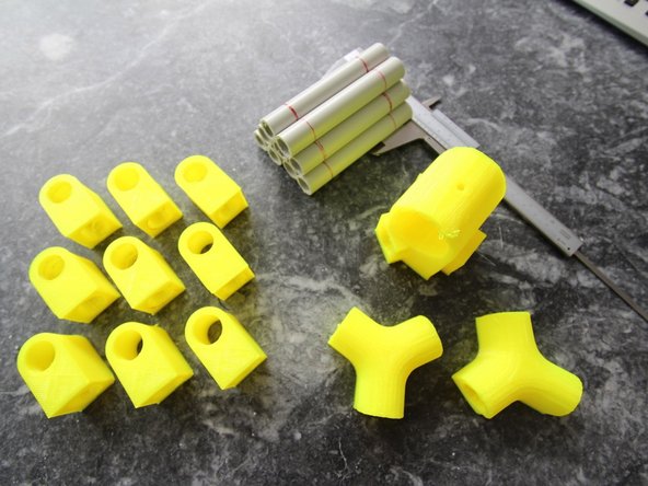
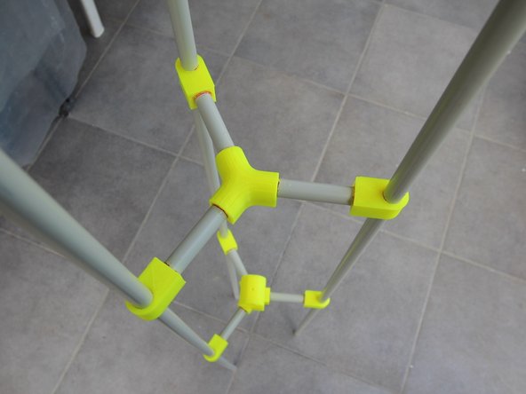
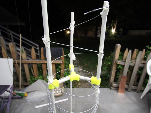
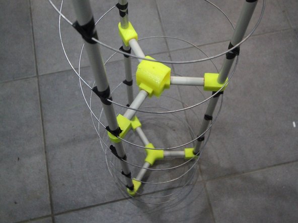
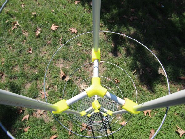
For the antenna structure assembly you will need everything from previous steps plus the following 3D printed parts:
-
9x T-connectors, 2x Y-connectors, 1x YO connector
-
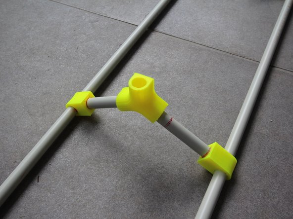
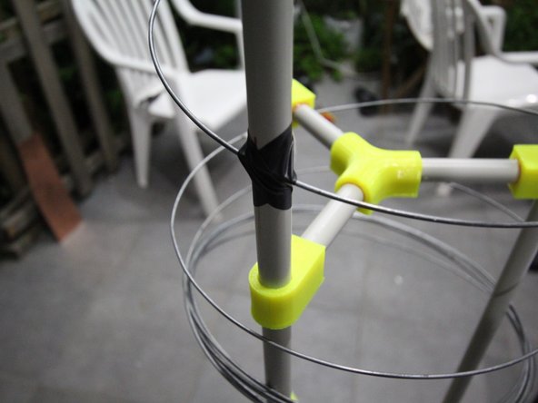
Put 6 of the T-connectors in place as shown, driven by the design.
-
Make sure not to put the 3 outer ones (as you will need to put the reflector first in place).
-
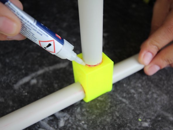
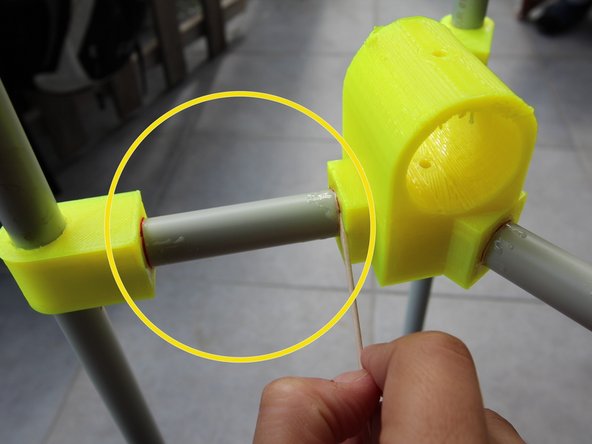
Using 6 small PVC pipes (see previous step) glue them in the 6 T-connectors as shown.
-
-
-
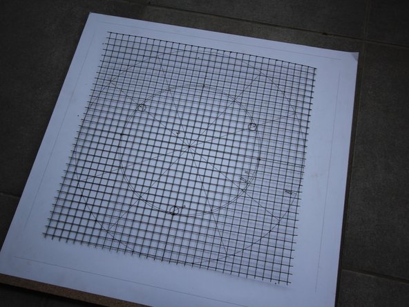
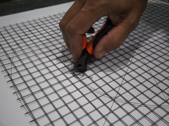
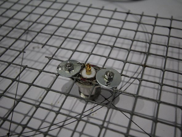
Take a galvanized steel grid of approx. 41x41cm.
-
Mark the holes for the PVC pipes with your printed design and cut the holes through the steel grid.
-
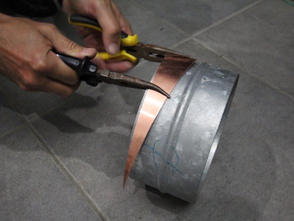
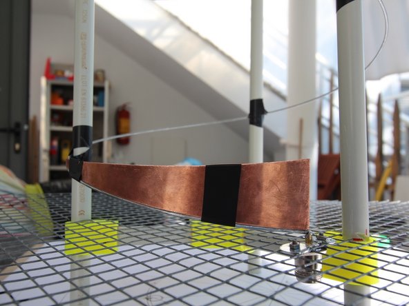
Bend the brass triangle (see bom) using the metal cylinder as a guide. Make sure it is bended on the right direction.
-
The brass triangle (ortho 204x41mm) will be used as a matching strip.
-
-
-
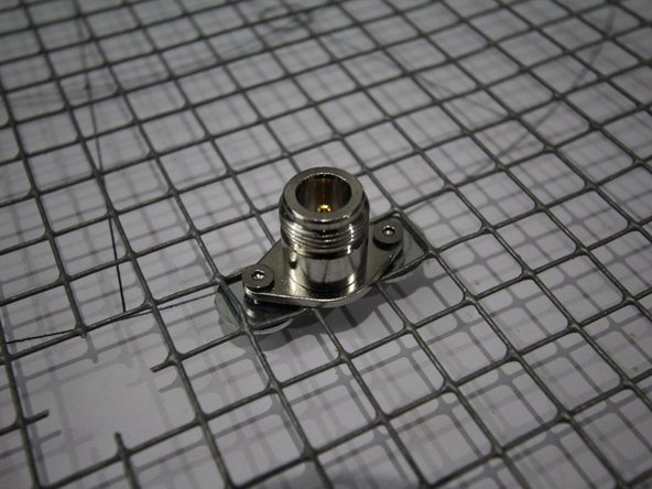
Next we will be installing the N-type connector to our ground plane.
-
Any N-type connector (or other connector you would like) can fit. Just make sure you are not short-circuiting the core with the outside casing.
-
In our case we are using 2x M3x10mm with 2xM3 nuts and 2x M4 washers (to fit our grid)
-
You can optionally solder the whole thing together, just to be on the safe side for the connection.
-
-
-
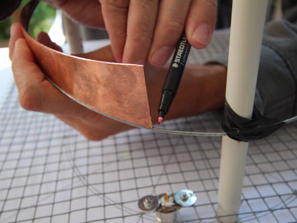
Using the brass triangle as a guide mark the end of the wire
-
Consult the design for the exact location of the grid along the pipes, and make sure you account for the N-type connector location (and core height)
-
Using sand paper, scrap off the galvanized coating of the wire. This will make soldering possible.
-
Secure the brass triangle in place (see designs too) with tape. You can either choose to cut the wire or use it along the triangle. (depends on how you will solder, and how comfortable you are with it)
-
Best matching of the signal will be achieved with a smooth transition from the wire to the triangle and then to the n-type core.
-
-
-
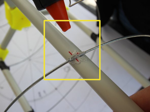
Start removing the black tape that holds the wire on the pipes.
-
Using a glue gun, secure the wires in place. You can add some tape on top of it for additional securing.
-
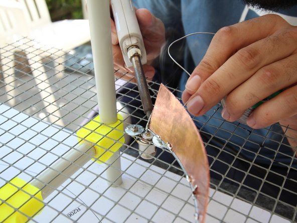
Solder the triangle on the wire as shown, or cut the wire and solder the triangle end to end with n-type and wire.
-
Your Helical antenna should now be ready!
-


Cancel: I did not complete this guide.
One other person completed this guide.

One Comment
I am building a groundstation to detect signals from cubesats or other signals in 420 - 450 MHz, but I do not see any signals.
I make a helical antenna with 10 dBi and I use a USRP to control the SDR. In the first part of detections, I need to see only the temporary signals on spectrum analyzer, due to the Cubesats pass for 10 minutes. But I can't see.
I tested the antenna, sending a carrier through the signal generator and it is OK. The USRP has a sensitivity of -110 dBm, using its amplifiers. Besides that I bought two LNAs with 20 and 24 dB of gain, ans it is not enough.
What I need to do more?
Regards and thank you for this great project!!
Fabricio Silva.