Introduction
Notes:
*Some of the pictures in this guide are from previous versions of the rotator.
-
-
In this step we are constructing the frame.
-
You will need 4x T slot 20x20 L160, 9x T slot 20x20 L102, 20x Hidden corner connection slot 6.
-
Start by assembling using a 2mm Allen key.
-
Beware of the correct hidden corner connection orientation.
-
You can find the assembly diagram on the next step.
-
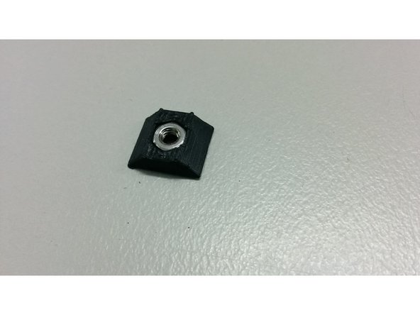
If you purchased square nuts that only fit into the slot from the end, be sure to insert them before assembling the frame with the hidden corners.
-
-
-
You should now have a complete frame.
-
Make sure you dont fasten the holding connectors for the extra L102 beam on one side.
-
Beware of the orientation (short side vs long side) of the hidden corners!
-
-
-
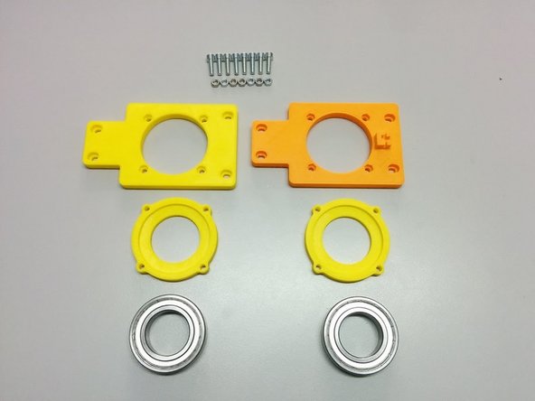
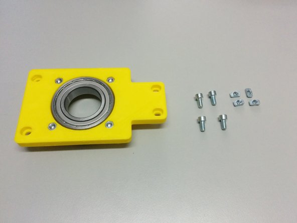
For this step you will need:
-
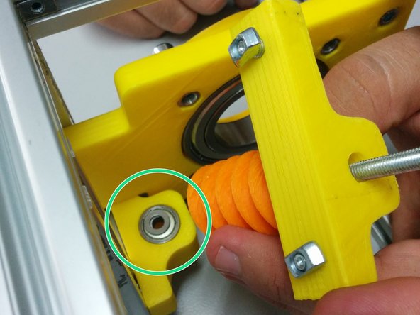
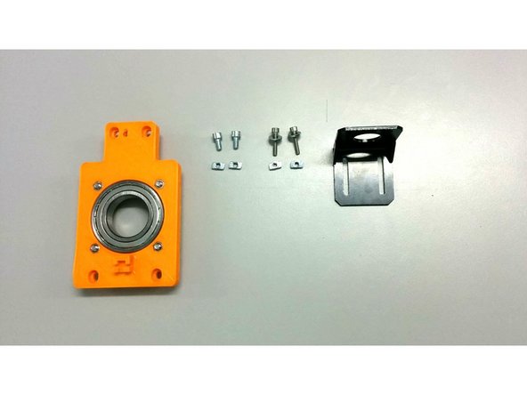
3D printed: Axis side with homing sensor (older version shown in the picture), Axis side, 2x Ball bearing housing
-
8x M4-20 screws, 8x M4 nuts
-
2x Ball Bearing 6008ZZ
-
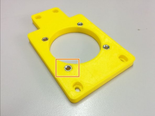
Insert the 8 nuts in the pockets of the axis sides.
-
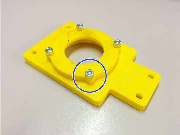
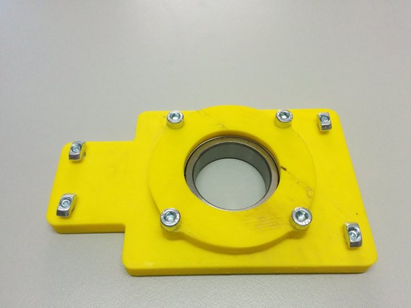
Attach the ball bearing housings on the back of each axis side and fasten it with M4-20 screws as shown.
-
-
-
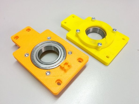
Finally, place the ball bearings inside the pockets created.
-
-
-
In this step you will need:
-
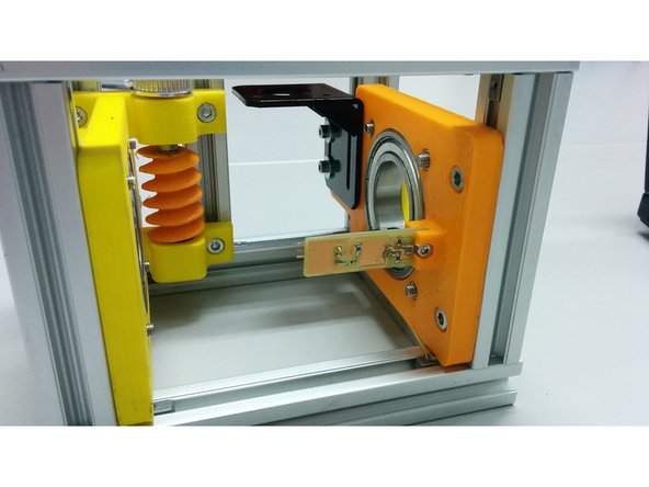
1x side assembly (the one without the homing sensor holder)
-
4x M4 slot 6 nuts, 4x M4-10 bolts
-
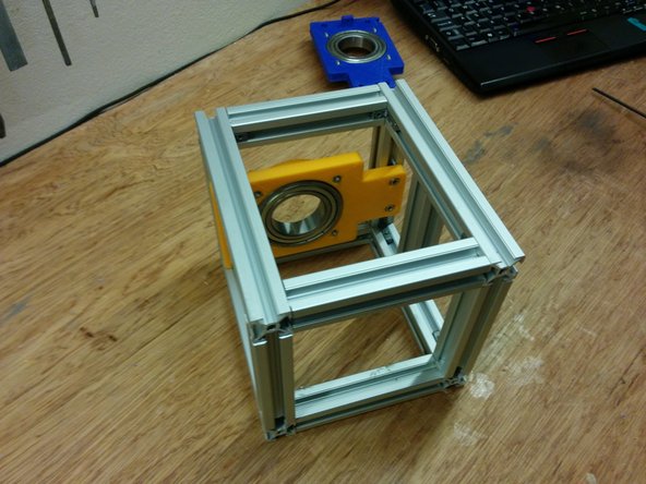
Screw the M4-10 bolts through the side assembly as shown on the second picture and attach the M4 slot 6 nuts
-
Finally slide the whole piece inside the frame as shown (bottom side touching the frame) and secure it by screwing the 4 M4-10 bolts.
-
-
-
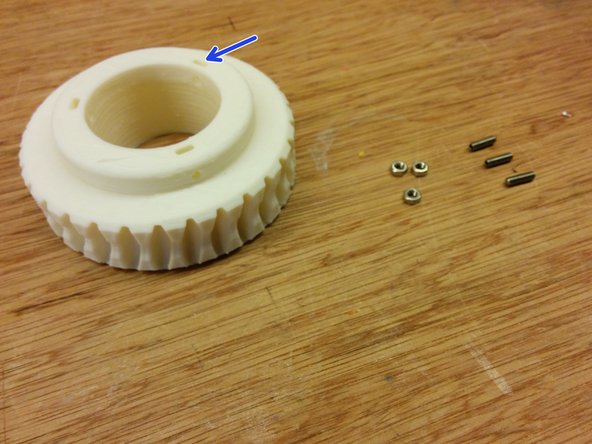
In this step you will need:
-
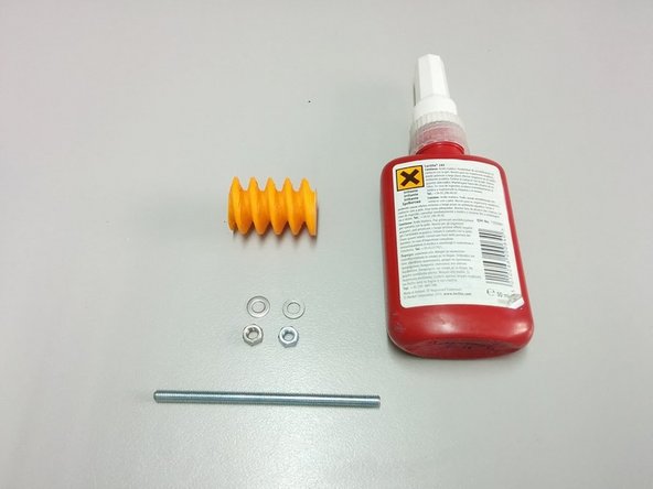
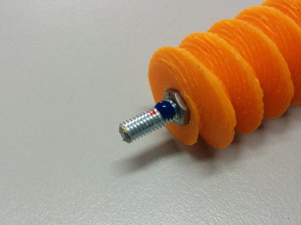
3D Printed: Worm gear
-
Thread lock glue
-
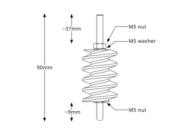
2x M5 nut, 1x M5 washer (wrong in the picture), 90mm M5 threaded rod
-
Apply glue as shown.
-
Follow the diagram for the dimensions.
-
-
-
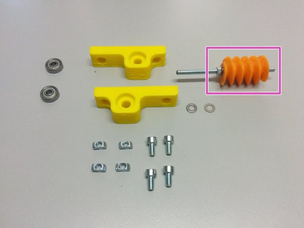
In this step you will need:
-
The previous worm gear assembly.
-
3D Printed: Worm mount
-
2 ball bearings 625ZZ
-
4x M4 nut slot 6, 4x M4-10 screws, 2x M4 washer.
-
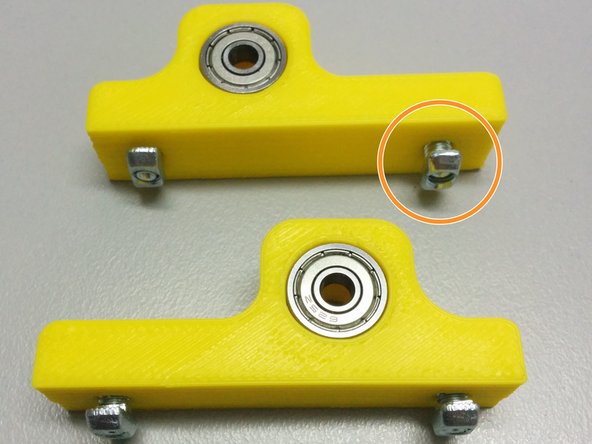
Insert the ball bearings inside the pockets of the mounts. Then screw the bolts into the nuts slot6 as shown in the pic.
-
Finally slide the worm mounts in the slot 6 rails as shown. First the one without the gear assembly first, then the second with the gear assembly as shown.
-
Don't forget the washers between the ball bearings and the worm gear assembly.
-
-
-
In this step you will need:
-
The second axis side assembly (the one with the homing sensor holder)
-
2x M4 slot6 nuts, 2x M4-10 bolts
-
2x M4 slot6 nuts, 2x M4-20 bolts
-
The motor mount.
-
Attach the bolts, slot 6 nuts and the stepper motor mount.
-
Finally attach the whole assembly to the frame as shown in the picture.
-
-
-
In this step you will need:
-
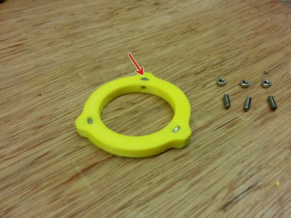
3D printed: Axis spacer collar
-
3x M3 nut, 3x M3-10 set screws
-
Insert the nuts in the pockets of 3d printed part, then screw the set screws as shown.
-
-
-
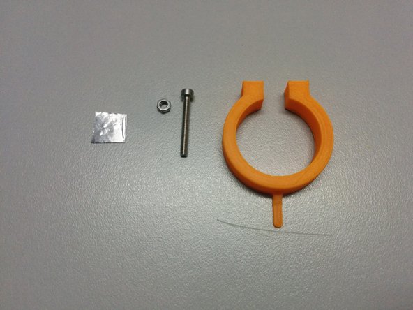
You will need:
-
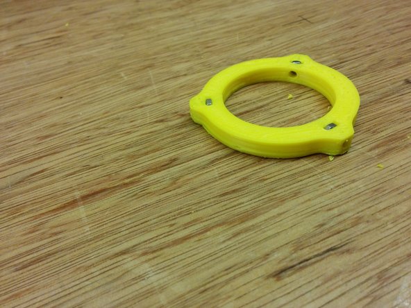
The homing ring part
-
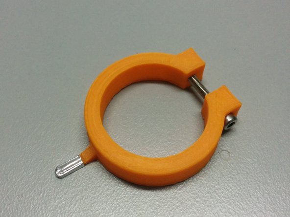
1x M3 nut, 1x M3-25 bolt.
-
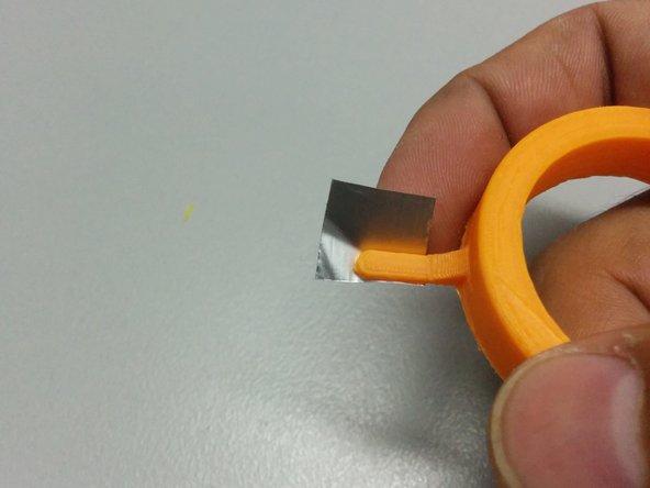
One small piece of aluminum tape (or something that blocks the IR light)
-
-
-
Insert the M3 nuts to axis gear part.
-
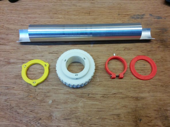
Pass the axis through:
-
Axis collar spacer
-
Homing ring
-
Axis gear
-
Axis spacer
-
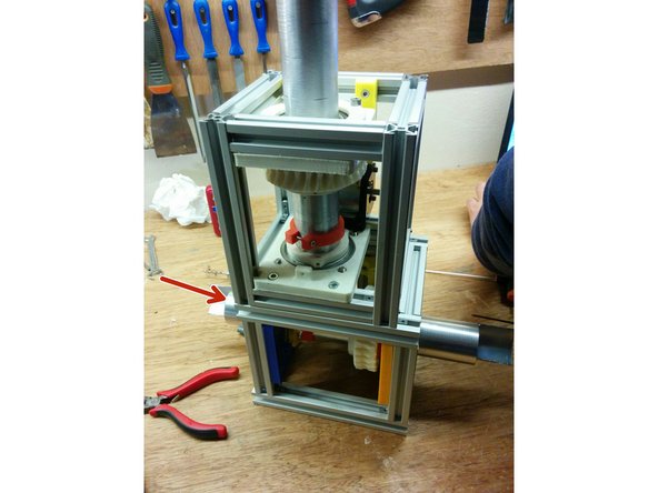
-
-
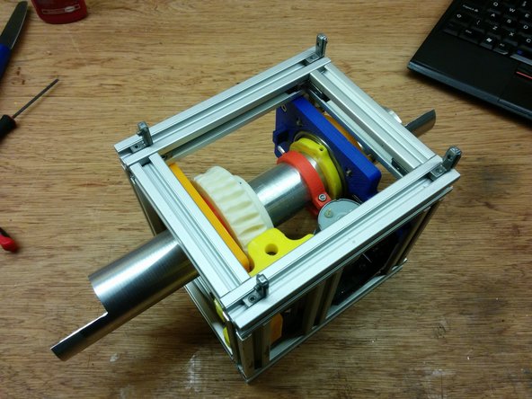
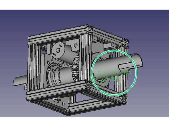
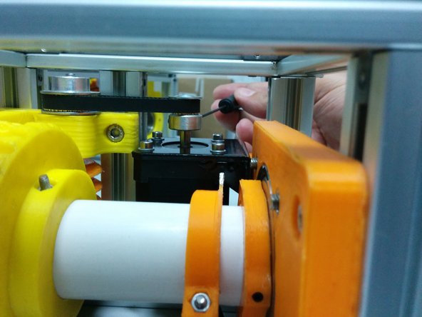
Ensure that the distance from the tube to the frame is approximately 54mm as shown in the first image.
-
Tight all screws on axis gear part.
-
Apply some silicone grease on the axis gear and use a power drill to slowly run the worm gear for a couple of minutes in both directions .
-
-
-
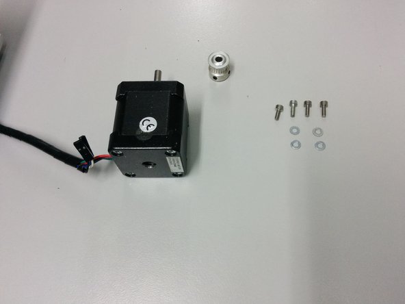
In this step you will need:
-
4x M3-6 and 4x M3 washers
-
NEMA 17 stepper motor
-
GT2 pulley 20 T 5mm bore and GT2 pulley 36 T 5mm bore (not shown on the first picture)
-
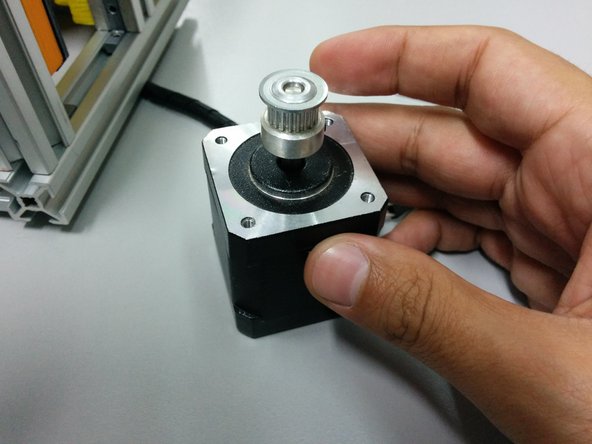
Pass the small pulley through the stepper motor shaft and the larger through the worm shaft.
-
Place the motor under the mount and tighten the screws.
-
-
-
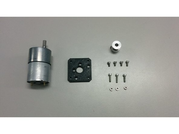
In this step you will need:
-
3x M3 nuts
-
4x M3-6 Head cap screws
-
3x M3-12 Head cap screws
-
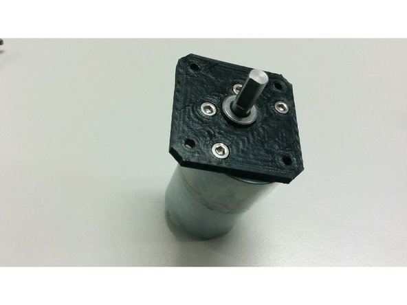
3D printed part motor_mount_flange
-
GT2 pulley 20 T 6mm bore and GT2 pulley 36 T 5mm bore (not shown on the pics)
-
Bolt the motor on the flange
-
Insert the small pulley over the motor shaft and the larger through the worm shaft. Bolt the flange, with the motor, on the motor base.
-
-
-
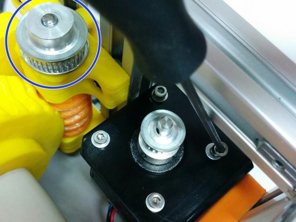
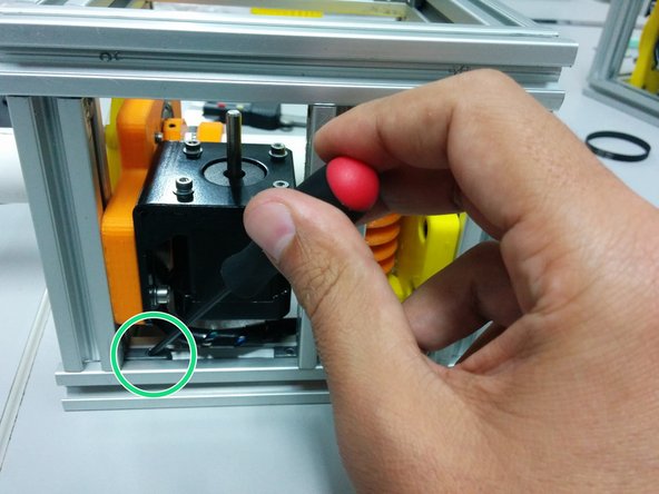
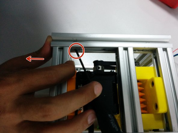
Loose the screws on the hidden corners in a way that stepper motor can slide towards the worm gear.
-
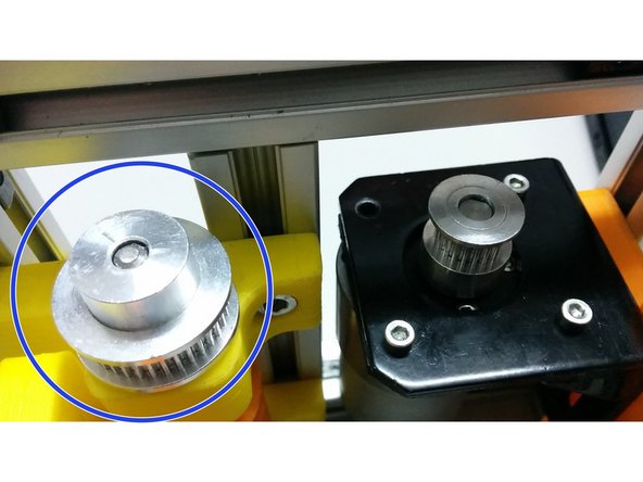
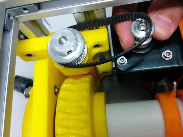
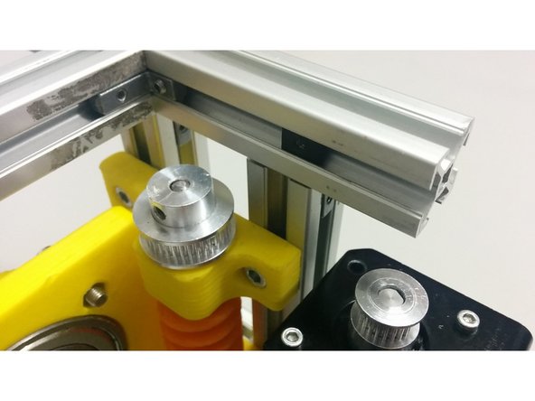
Place the the GT2 timing belt 158mm between the worm and motor pulleys.
-
Align the height of the pulleys and secure the pulleys on the axis.
-
-
-
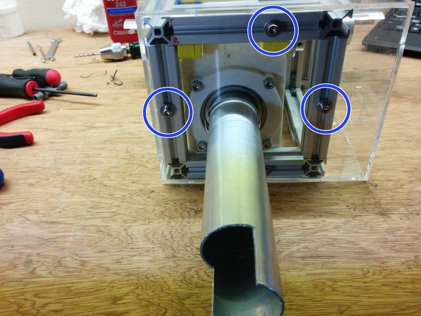
Slide the axis side to tighten the belt and secure the screws and hidden corners
-
Push the axis spacer collar onto the bearing and tighten the screws.
-
-
-
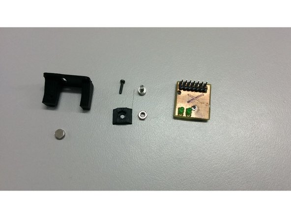
In this step you will need:
-
1x M3 nut
-
1x M3-6 Head cap screw
-
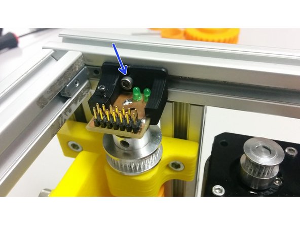
1x M2-6 Thread-Forming Screw
-
SatNOGS encoder board
-
1x D6x2.5 Neodymium Diametric Magnet
-
And 3D printed parts: M3_TSlot20_nut, encoder_holder
-
Place the nut into the 3D printed part and slide it into the aluminum profile
-
-
-
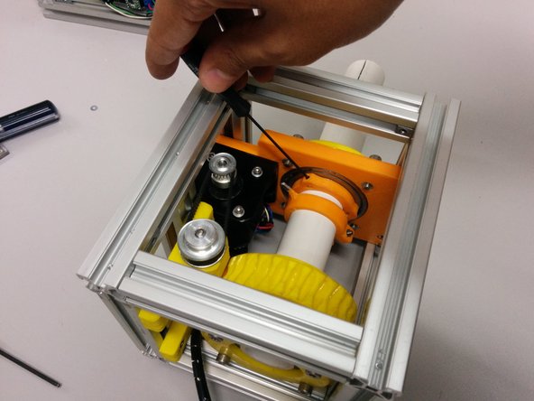
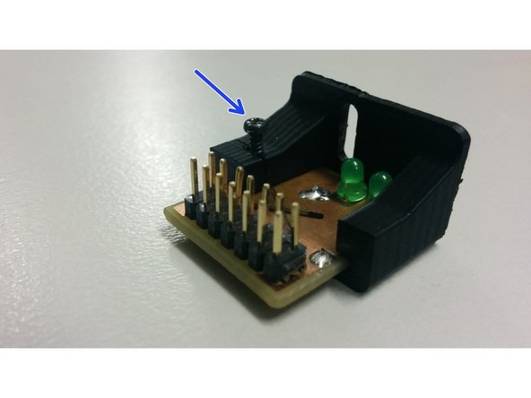
Slide The pcb into the 3D printed part and use the M2 screw to gently hold it in place
-
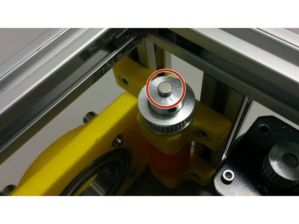
Using some cyanoacrylate glue, fix the magnet over the center of the pulley that is over the worm gear
-
Bolt and align the encoder over the magnet using the M3 screw
-
-
-
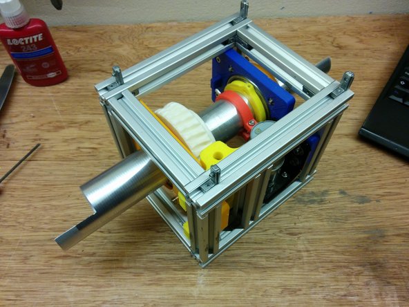
Assemble the elevation axis like the previous one.
-
Slide the hidden corners in the bottom side of the elevation axis as shown at the first picture.
-
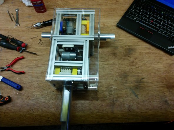
Place the azimuth axis on top of the elevation in a way that the extension of the azimuth axis intersects with the elevation axis. The motors should be on the same side. Slide to the one side as shown in the picture.
-
-
-
Insert the bottom side of the case and secure it using 4xM4-10 bolts 4xM4 T-slot nuts and 4xM4 washers
-
Place the upper side of the cover.
-