-
-
In this step we are constructing the frame.
-
You will need 4x T slot 20x20 L160, 9x T slot 20x20 L102, 20x Hidden corner connection slot 6.
-
Start by assembling using a 2mm Allen key.
-
Beware of the correct hidden corner connection orientation.
-
You can find the assembly diagram on the next step.
-
If you purchased square nuts that only fit into the slot from the end, be sure to insert them before assembling the frame with the hidden corners.
-
-
-
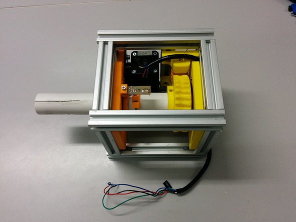
You should now have a complete frame.
-
Make sure you dont fasten the holding connectors for the extra L102 beam on one side.
-
Beware of the orientation (short side vs long side) of the hidden corners!
-
-
-
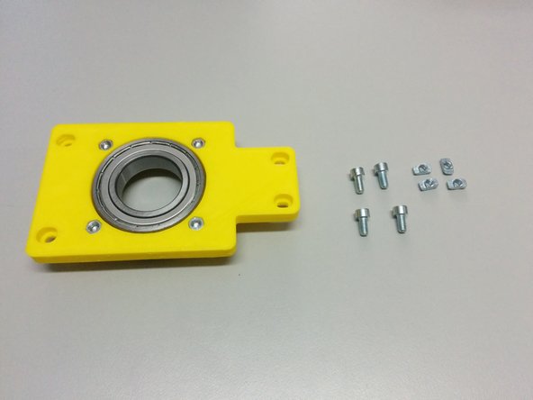
For this step you will need:
-
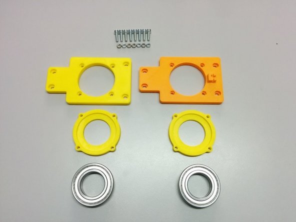
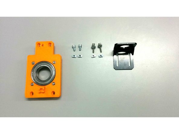
3D printed: Axis side with homing sensor, Axis side, 2x Ball bearing housing
-
8x M4-20 screws, 8x M4 nuts
-
2x Ball Bearing 6008ZZ (or appropriate for your tube diameter)
-
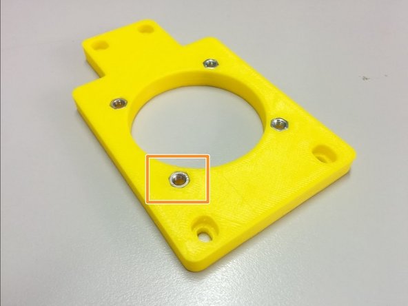
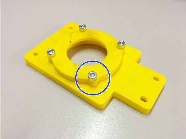
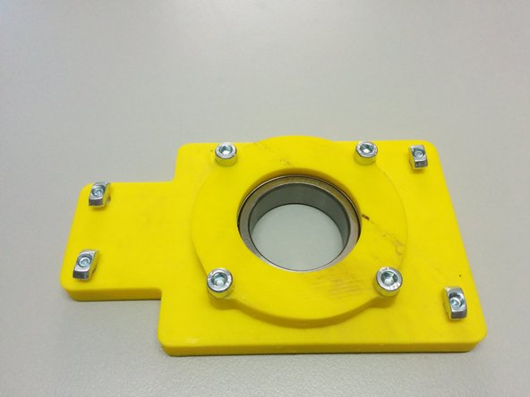
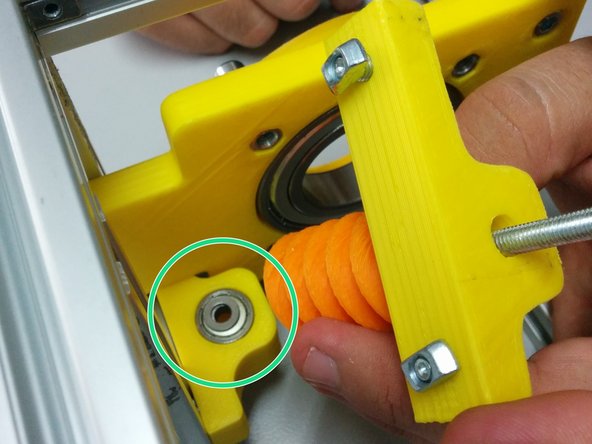
Insert the 8 nuts in the pockets of the axis sides.
-
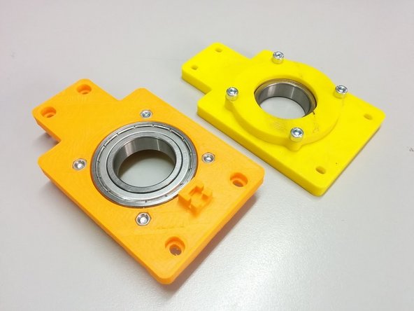
Attach the ball bearing housings on the back of each axis side and fasten it with M4-20 screws as shown.
-
-
-
Finally, place the ball bearings inside the pockets created.
-
-
-
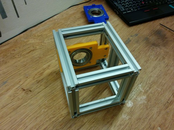
In this step you will need:
-
1x side assembly (the one without the homing sensor holder)
-
4x M4 slot 6 nuts, 4x M4-10 bolts
-
Screw the M4-10 bolts through the side assembly as shown on the second picture and attach the M5 slot 6 nuts
-
Finally slide the whole piece inside the frame as shown (bottom side touching the frame) and secure it by screwing the 4 M4-10 bolts.
-
-
-
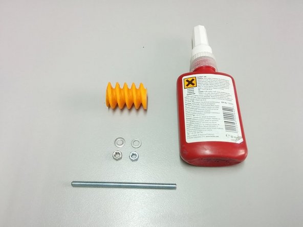
In this step you will need:
-
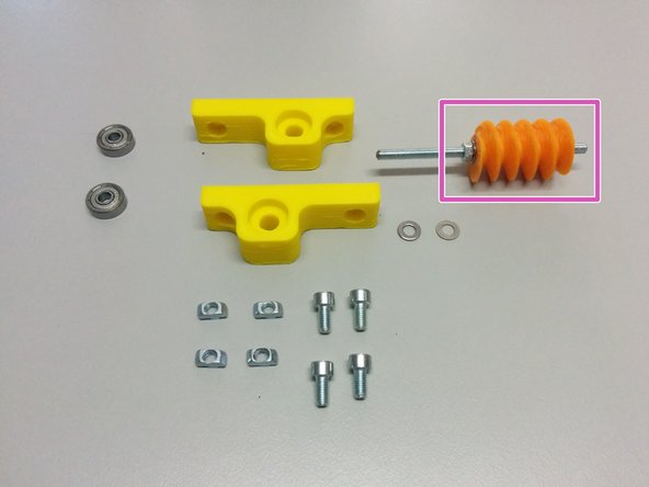
3D Printed: Worm gear
-
Thread lock glue
-
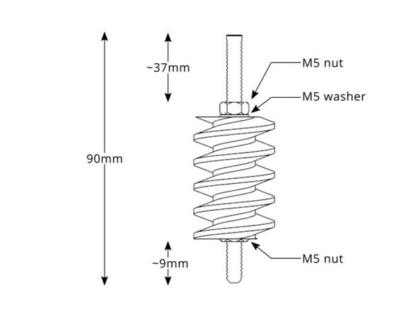
2x M5 nut, 1x M5 washer (wrong in the picture), 90mm M5 threaded rod
-
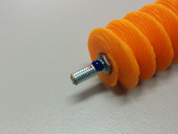
Apply glue as shown.
-
Follow the diagram for the dimensions.
-
-
-
In this step you will need:
-
The previous worm gear assembly.
-
3D Printed: Worm mount
-
2 ball bearings 625ZZ
-
4x M4 nut slot 6, 4x M4-10 screws, 2x M4 washer.
-
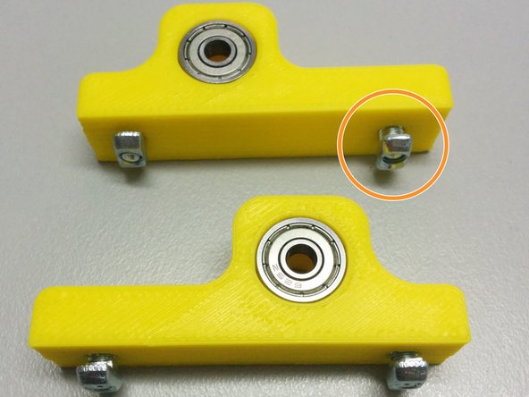
Insert the ball bearings inside the pockets of the mounts. Then screw the bolts into the nuts slot6 as shown in the pic.
-
Finally slide the worm mounts in the slot 6 rails as shown. First the one without the gear assembly first, then the second with the gear assembly as shown.
-
Don't forget the washer between the ball bearings and the worm gear assembly.
-
-
-
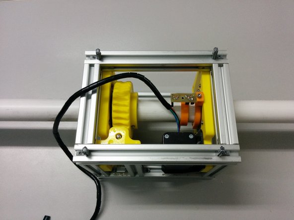
In this step you will need:
-
The second axis side assembly (the one with the homing sensor holder)
-
2x M5 slot6 nuts, 2x M5-10 bolts
-
2x M4 slot6 nuts, 2x M4-20 bolts
-
The stepper motor mount.
-
Attach the bolts, slot 6 nuts and the stepper motor mount.
-
Finally attach the whole assembly to the frame as shown in the picture.
-
-
-
You will need:
-
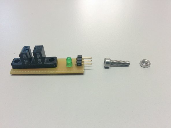
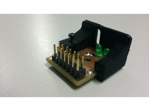
The homing sensor electronic circuit
-
1x M3 nut, 1x M3-12 bolt, 1x M3 washer (not shown)
-
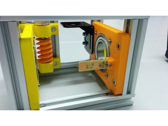
Mount the homing sensor on the axis mount as shown.
-
-
-
In this step you will need:
-
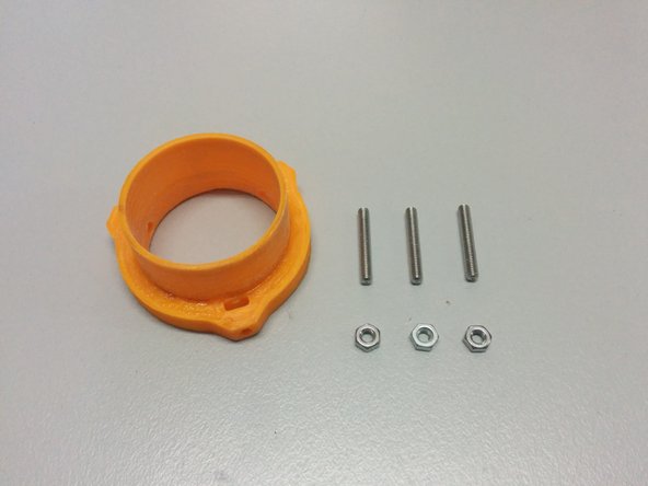
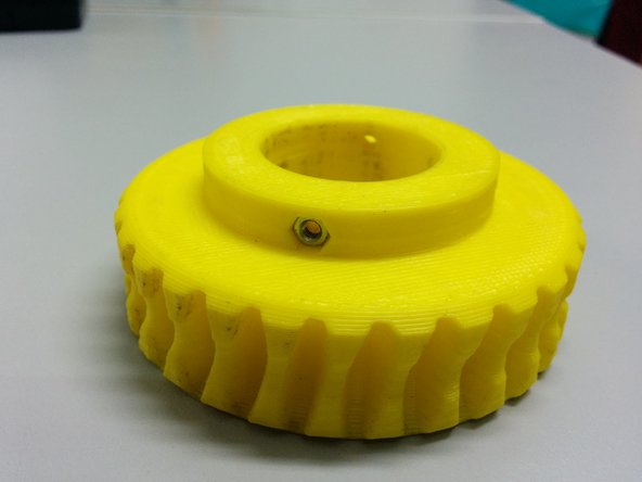
3D printed: Axis spacer collar
-
3x M3 nut, 3x M3-10 set screws
-
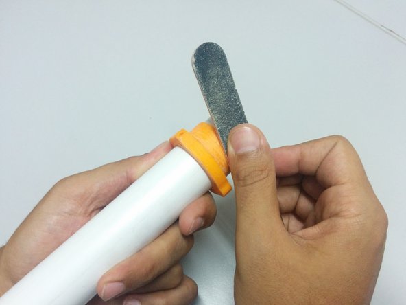
Insert the nuts in the pockets of 3d printed part, then screw the set screws as shown.
-
You may need to sand the final surface of your 3D printed part (check how it fits inside the side ball bearings.
-
-
-
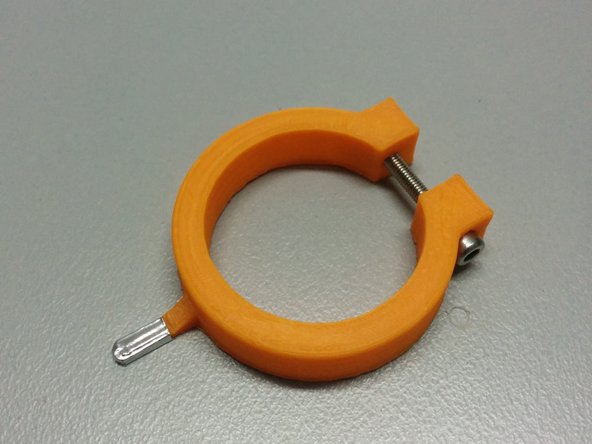
You will need:
-
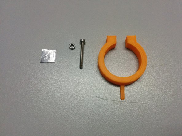
The homing ring part
-
1x M3 nut, 1x M3-25 bolt.
-
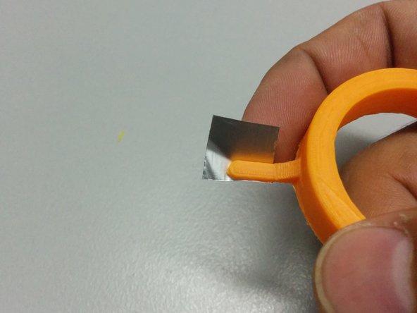
One small piece of aluminum tape (or something that blocks the IR light)
-
-
-
Insert the M3 nut to axis gear part.
-
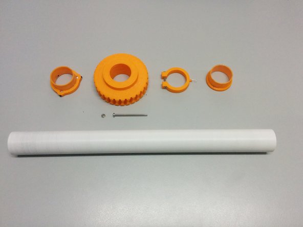
Pass the axis through:
-
Axis collar spacer
-
Homing ring
-
Axis gear
-
Warning: Make sure the hole is facing the top.
-
Axis spacer
-
-
-
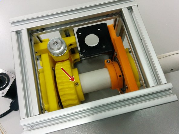
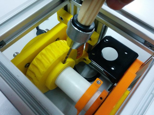
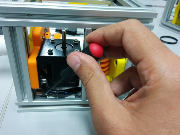
Tighten the alen bolts on the axis spacer collar part.
-
Open a 3mm hole on the axis and tighten the M3-50.
-
Align the homing ring pin to the homing sensor and tighten the screw.
-
-
-
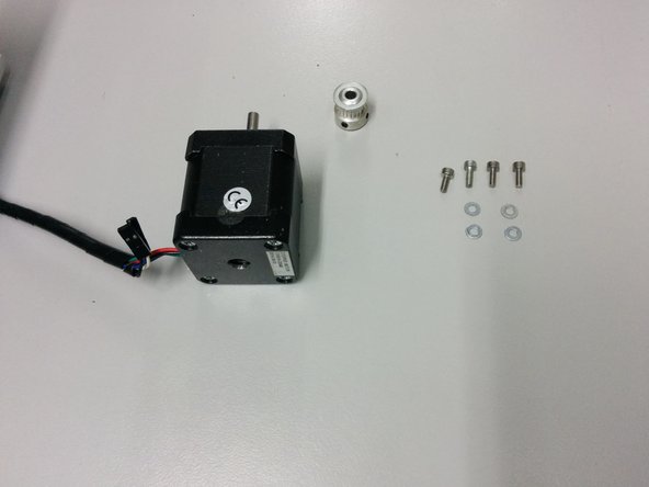
In this step you will need:
-
4x M3-6 /w washers
-
NEMA 17 stepper motor
-
GT2 pulley 20 tooth 5mm bore
-
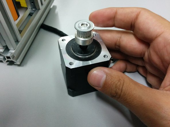
Pass the pulley through the stepper motor shaft
-
Place the motor under the mount and tighten the screws.
-
-
-
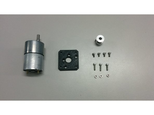
In this step you will need:
-
3x M3 nuts
-
4x M3-6 Head cap screws
-
3x M3-12 Head cap screws
-
3D printed part motor_mount_flange
-
GT2 pulley 20 tooth 6mm bore
-
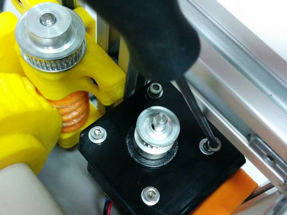
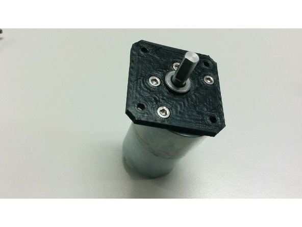
Bolt the motor on the flange
-
Insert the pulley over the motor shaft and bolt the flange, with the motor, on the motor base.
-
-
-
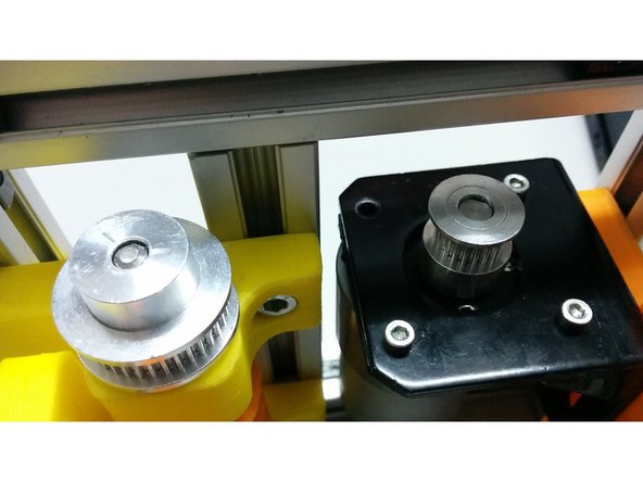
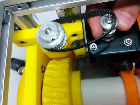
Loose the screws on the hidden corners in a way that stepper motor can slide towards the worm gear.
-
Place the the GT2 timing belt 158mm between the worm and motor pulleys.
-
Align the height of the pulleys and secure the pulley on the axis.
-
-
-
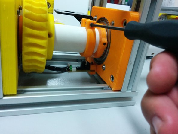
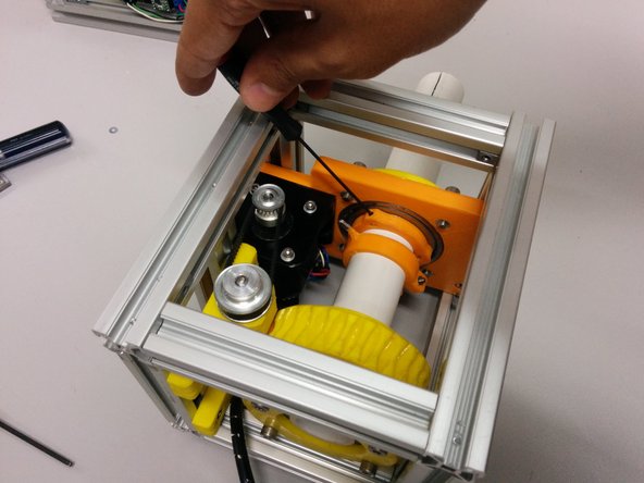
Slide the axis side to tighten the belt and secure the screws and hidden corners
-
Push the axis spacer collar onto the bearing and tighten the screws.
-
We are going to need:
-
40cm of wire for endstops
-
Connector for triple pin header
-
35 cm cable manager
-
Use cable manager to manage endstop and stepper motor cables.
-
Connect the endstop.
-
-
-
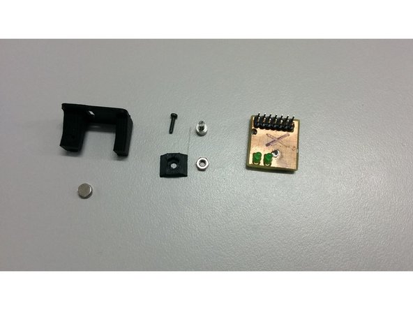
In this step you will need:
-
1x M3 nut
-
1x M3-6 Head cap screw
-
1x M2-6 Thread-Forming Screw
-
SatNOGS encoder board
-
1x D6x2.5 Neodymium Diametric Magnet
-
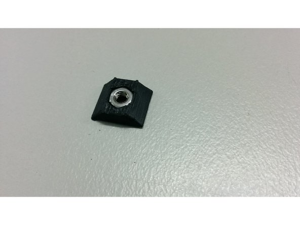
And 3D printed parts: M3_TSlot20_nut, encoder_holder
-
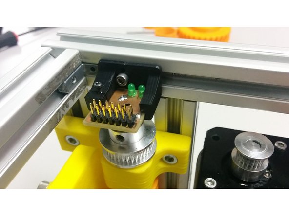
Place the nut into the 3D printed part and slide it into the aluminum profile
-
-
-
Slide The pcb into the 3D printed part and use the M2 screw to gently hold it in place
-
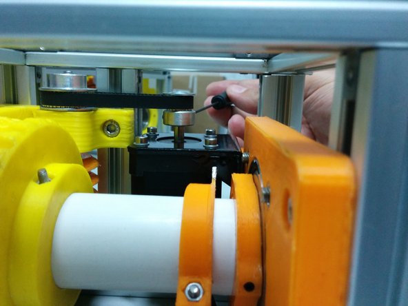
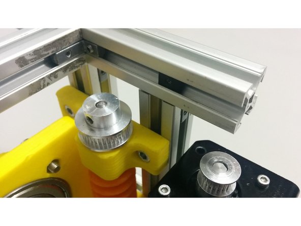
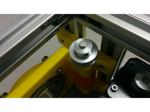
Using some cyanoacrylate glue, fix the magnet over the center of the pulley that is over the worm gear
-
Bolt and align the encoder over the magnet using the M3 screw
-
-
-
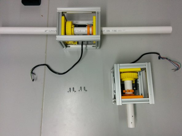
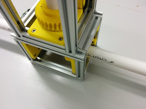
Assemble the elevation axis like the previous one. The only difference is that the length of t-slots that are parallel to the axis is 180mm and the timing belt is 202 mm.
-
Slide the hidden corners in the bottom side of the elevation axis.
-
Place the azimuth axis on top of the elevation in a way that the extension of the azimuth axis intersects with the elevation axis. Center it in the other direction.
-
-
-
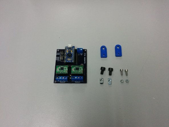
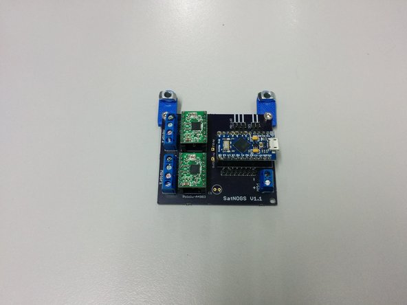
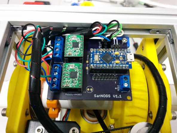
In this step you need
-
Assembled satnogs PCB controller
-
2x M5-14 screws, 2xM5 t-slot nuts
-
2x M3-10 screws, 2xM3 nuts
-
Make sure you are using the latest controller that can be found here https://github.com/satnogs/satnogs-rotat...
-
The controller depicted is an older version.
-