-
-
In this step we are constructing the frame.
-
You will need 4x T slot 20x20 L160, 9x T slot 20x20 L102, 20x Hidden corner connection slot 6.
-
Start by assembling using a 2mm Allen key.
-
Beware of the correct hidden corner connection orientation.
-
You can find the assembly diagram on the next step.
-
-
-
You should now have a complete frame.
-
Make sure you dont fasten the holding connectors for the extra L102 beam on one side.
-
Beware of the orientation (short side vs long side) of the hidden corners!
-
-
-
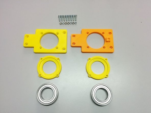
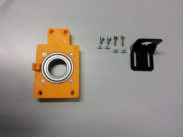
For this step you will need:
-
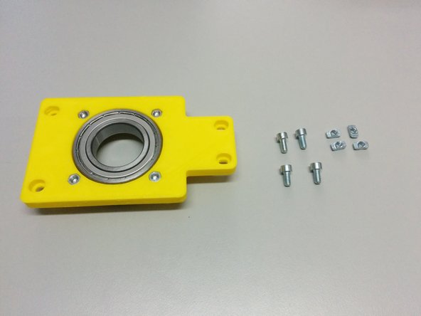
3D printed: Axis side with homing sensor, Axis side, 2x Ball bearing housing
-
8x M5-20 screws, 8x M5 nuts
-
2x Ball Bearing 6007ZZ
-
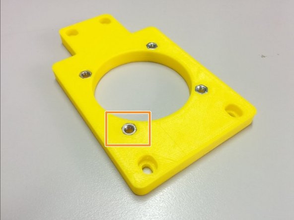
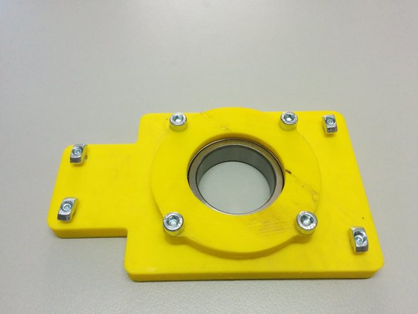
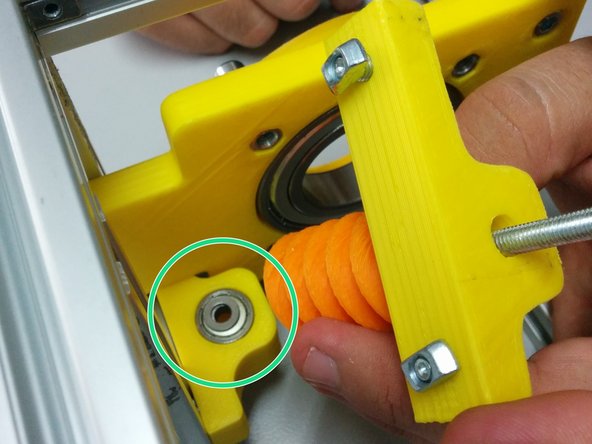
Insert the 8 nuts in the pockets of the axis sides.
-
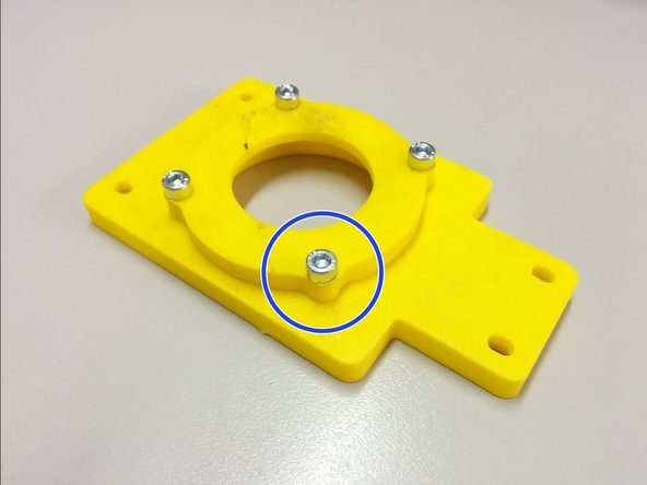
Attach the ball bearing housings on the back of each axis side and fasten it with M5-20 screws as shown.
-
-
-
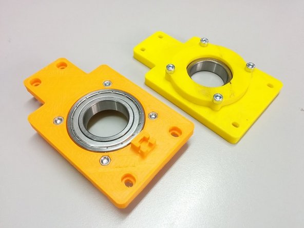
Finally, place the ball bearings inside the pockets created.
-
-
-
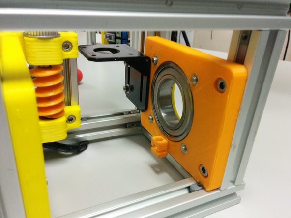
In this step you will need:
-
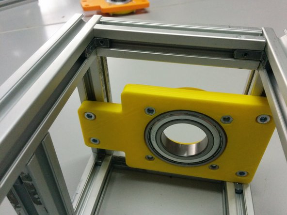
1x side assembly (the one without the homing sensor holder)
-
4x M5 slot 6 nuts, 4x M5-10 bolts
-
Screw the M5-10 bolts through the side assembly as shown on the second picture and attach the M5 slot 6 nuts
-
Finally slide the whole piece inside the frame as shown (bottom side touching the frame) and secure it by screwing the 4 M5-10 bolts.
-
-
-
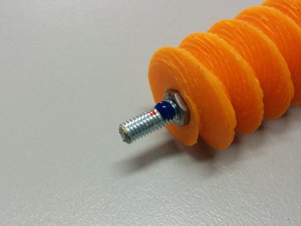
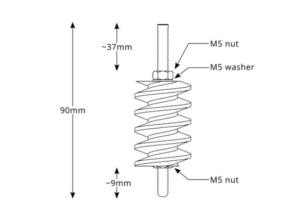
In this step you will need:
-
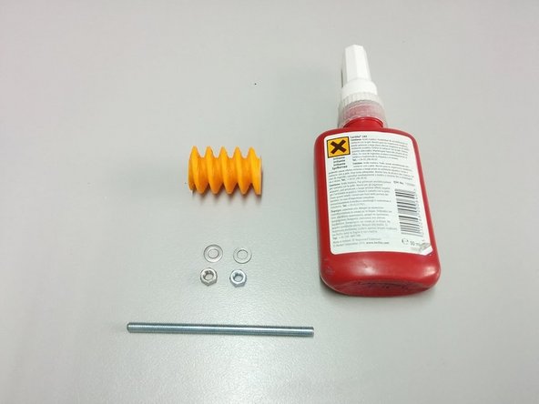
3D Printed: Worm gear
-
Thread lock glue
-
2x M5 nut, 2x M5 washer, 90mm M5 threaded rod
-
Apply glue as shown.
-
Follow the diagram for the dimensions.
-
-
-
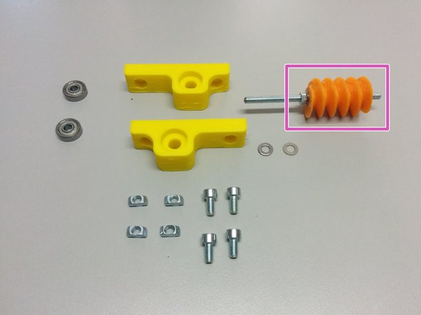
In this step you will need:
-
The previous worm gear assembly.
-
3D Printed: Worm mount
-
2 ball bearings 625ZZ
-
4x M5 nut slot 6, 4x M5-10 screws, 2x M5-10 washer.
-
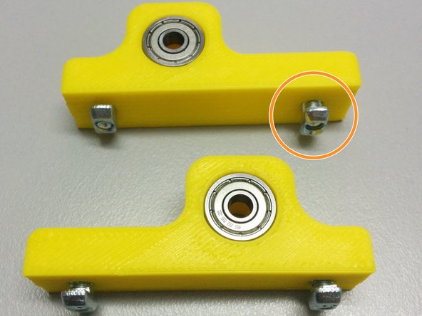
Insert the ball bearings inside the pockets of the mounts. Then screw the bolts into the nuts slot6 as shown in the pic.
-
Finally slide the worm mounts in the slot 6 rails as shown. First the one without the gear assembly first, then the second with the gear assembly as shown.
-
Don't forget the washer between the ball bearings and the worm gear assembly.
-
-
-
In this step you will need:
-
The second axis side assembly (the one with the homing sensor holder)
-
2x M5 slot6 nuts, 2x M5-10 bolts
-
2x M4 slot6 nuts, 2x M4-20 bolts
-
The stepper motor mount.
-
Attach the bolts, slot 6 nuts and the stepper motor mount.
-
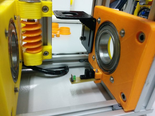
Finally attach the whole assembly to the frame as shown in the picture.
-
-
-
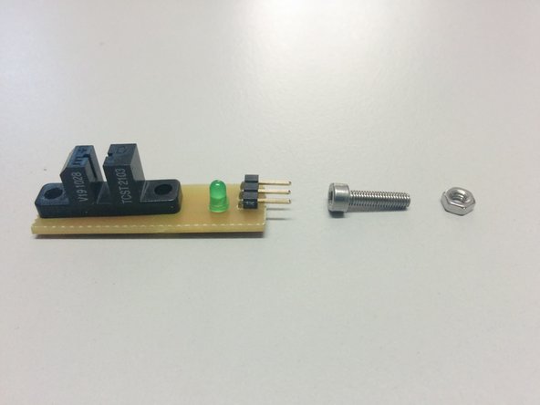
You will need:
-
The homing sensor electronic circuit
-
1x M3 nut, 1x M3-12 bolt, 1x M3 washer (not shown)
-
Mount the homing sensor on the axis mount as shown.
-
-
-
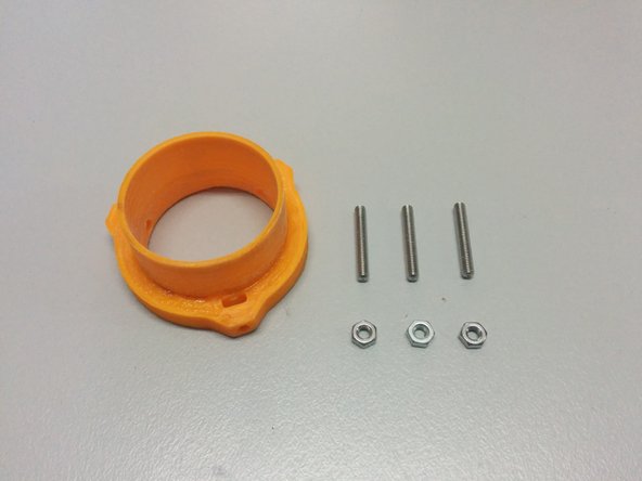
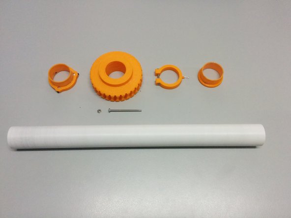
In this step you will need:
-
3D printed: Axis spacer collar
-
3x M3 nut, 3x M3-10 set screws
-
Insert the nuts in the pockets of 3d printed part, then screw the set screws as shown.
-
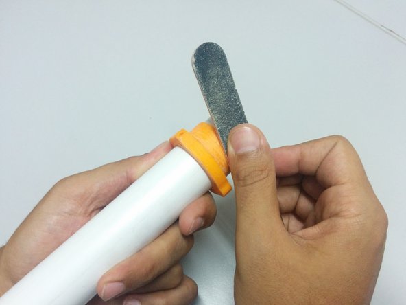
You may need to sand the final surface of your 3D printed part (check how it fits inside the side ball bearings.
-
-
-
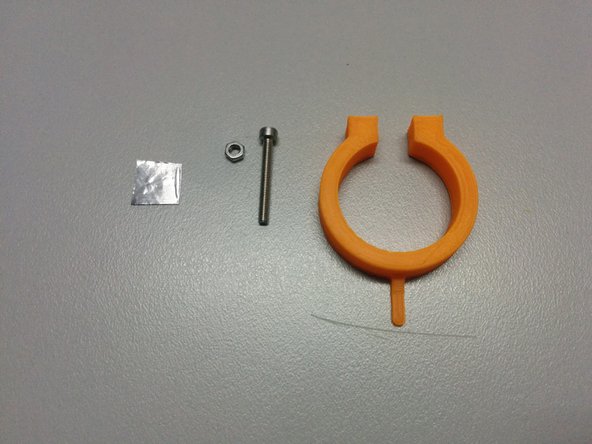
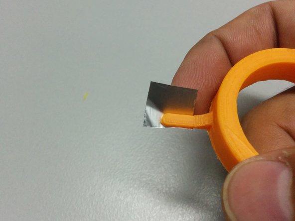
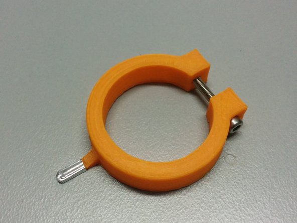
You will need:
-
The homing ring part
-
1x M3 nut, 1x M3-25 bolt.
-
One small piece of aluminum tape (or something that blocks the IR light)
-
-
-
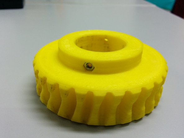
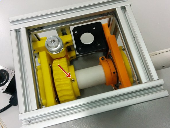
Insert the M3 nut to axis gear part.
-
Pass the access through:
-
Axis collar spacer
-
Homing ring
-
Axis gear
-
Warning: Make sure the hole is facing the top.
-
Axis spacer
-
-
-
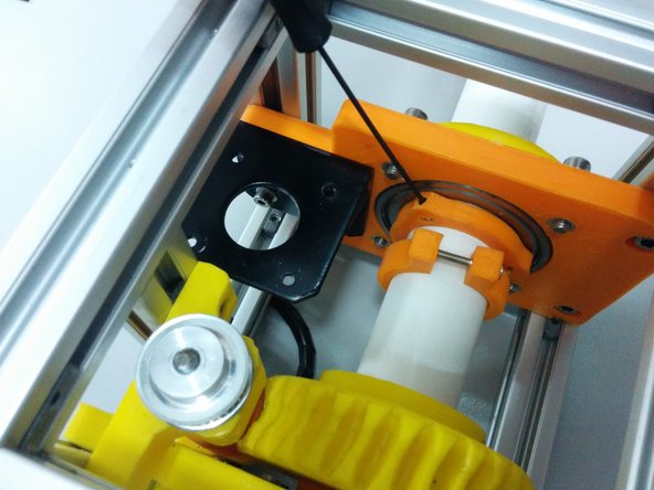
Tighten the alen bolts on the axis spacer collar part.
-
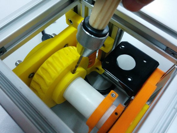
Open a 3mm hole on the axis and tighten the M3-50.
-
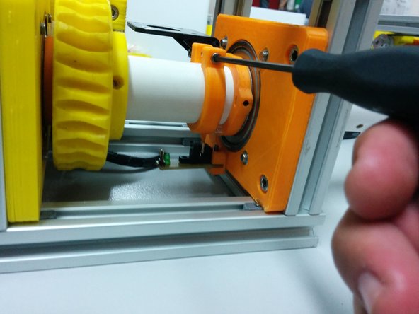
Align the homing ring pin to the homing sensor and tighten the screw.
-