-
-
Electronics Assembly You will need: CN: 电路组装
-
The SatNOGS v2 Mechanical Ground Station Assembly. CN: SatNOGS v2 的地面基站机械部分组装
-
TP-Link WR703N
-
SatNOGS PCB. CN: 印刷电路板部分,下同
-
SatNOGS PSU PCB
-
A 4 port USB hub. CN:4端口的USB hub
-
2 USB micro cables. CN: 2条USB迷你连接线
-
One double wire for 12V to SatNOGS PCB
-
-
-
Using double sided foam tape, place the TP Link on the side as shown.
-
Place SatNOGS PCB as shown (with foam tape)
-
Place SatNOGS PSU PCB as shown (with foam tape)
-
Stick with foam tape and connect the USB hub as shown.
-
-
-
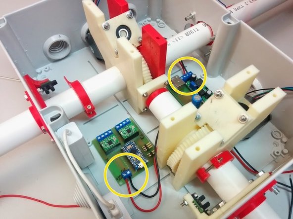
Wires are next:
-
Connect 12V from PSU PCB to PCB using two wires as shown.
-
Connect Stepper motor wires as shown.
-
Refer to Stepper motor documentation for specifics on colors of wires.
-
-
-
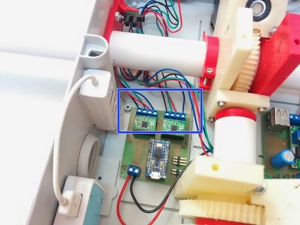
You will need 2 USB micro cables.
-
One USB micro cable should start from the PSU PCB and end to TP-Link (for power supply)
-
The other USB Micro cable should start from the USB Hub and end to the Arduino Micro (for data connection)
-
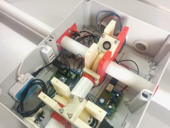
You have now finished all electronics setup of your Ground Station.
-